Handing GNSS survey coordinates to CAD teams without losing meaning
Package points and linework with reference definitions, units, feature codes and checks so CAD users can work from a coherent survey release.
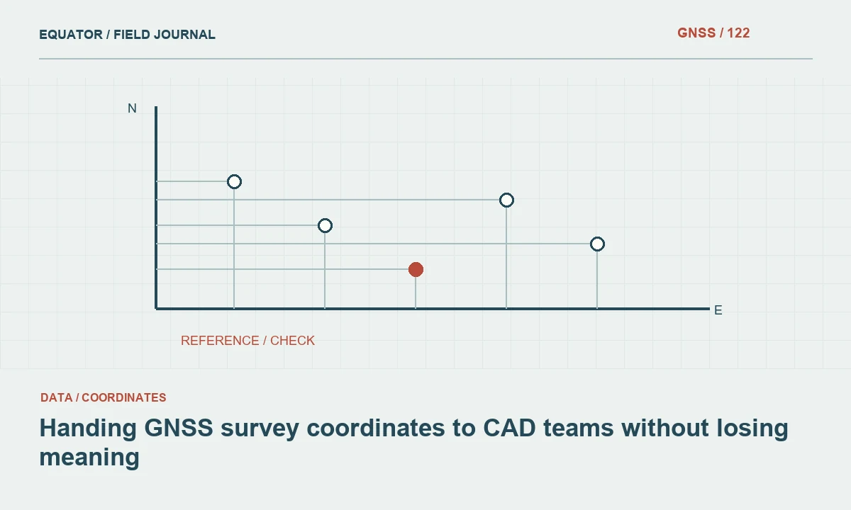
Define the CAD team’s required objects
Ask the receiving team which objects and formats they need before exporting. Points, breaklines, terrain surfaces and asset symbols have different meanings. A drawing containing point labels may not preserve the original point attributes or observation history. Agree whether the delivery is a survey base, a design reference or a presentation drawing.
Define the physical meaning of each feature code and elevation. A cover level, pipe invert and ground point should not become identical symbols with no distinction. Provide a code schedule and sample drawing early. A short exchange test can reveal whether the receiving workflow expects three-dimensional geometry, separate elevation attributes or another specific representation.
Continue learning Exporting GNSS data to GIS without losing its meaning
Confirm coordinate units and drawing conventions
Establish the units used by the survey coordinates and the receiving drawing. Review axis directions, origin and whether a local engineering grid is involved. A drawing may display numbers without carrying a complete CRS definition. Obtain the approved project reference rather than inferring it from the size of the coordinate values or the appearance of the plan.
Test a few known points after import. Check distances and elevations as well as map position. Unit errors can affect geometry even when labels look plausible. Keep the import mapping and any scale or transformation operation documented. Avoid applying a convenient drawing scale factor without understanding whether it is a display setting or an actual coordinate operation.
Continue learning Designing a geodatabase schema for GNSS point observations
Keep horizontal and vertical references explicit
Provide the source CRS, datum realisation, coordinate epoch where relevant and local grid definition. State the height type and any geoid or vertical transformation used. A generic elevation label is insufficient for engineering use. CAD users need to know whether the values represent ellipsoidal height, a project level or another defined vertical reference.
If the receiving drawing uses a different reference, transform through an approved operation and test the result on independent points. Preserve the original survey coordinates. Do not assign a new reference label or shift geometry by eye to fit a background. A visually aligned drawing can still be inconsistent with project control or a related terrain model.
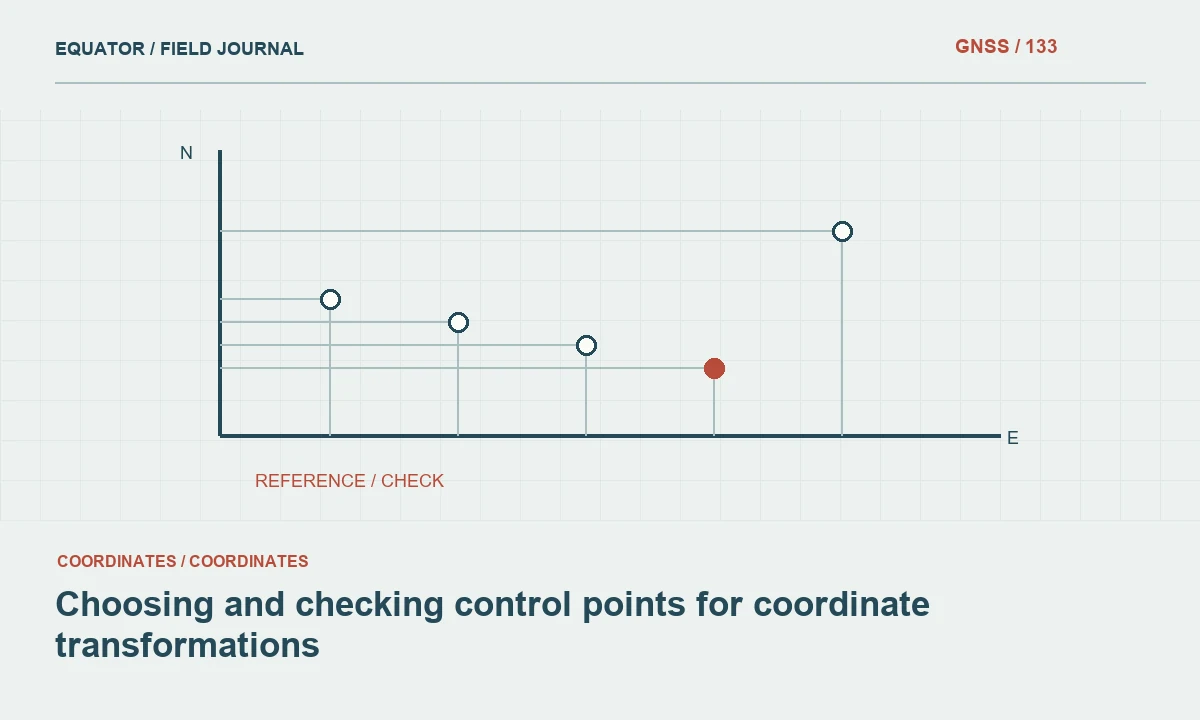
Continue learning Choosing and checking control points for coordinate transformations
Preserve identifiers and feature relationships
Keep stable point and asset identifiers through the export. Avoid replacing them with drawing object handles or labels that cannot be reconciled with the field record. If one asset has several observed points, preserve the relationship. Include feature codes, observation status and relevant descriptive attributes in an agreed form.
For connected linework, verify point order and breaks. A line should not cross a gap or join unrelated features merely because consecutive point numbers are close. Inspect junctions and parallel features carefully. The receiving team should understand which lines are directly observed, derived from observations or interpreted later. These distinctions can affect terrain modelling and design decisions.
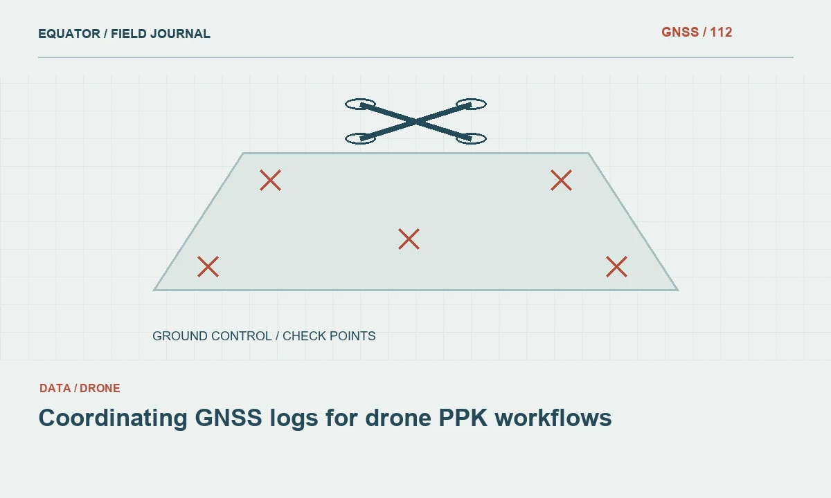
Continue learning Coordinating GNSS logs for drone PPK workflows
Separate survey geometry from annotation
Use layers or another agreed structure to distinguish measured features, control, text, symbols and derived surfaces. Annotation is useful, but it should not be the only place where important values exist. A displayed elevation rounded for readability may differ from the stored coordinate. Explain the relationship so recipients do not digitise labels as though they were the original measurements.
Keep presentation adjustments separate from geometry. Moving a label to avoid overlap is different from moving the associated survey point. If a symbol uses an insertion point or scale convention, document it. A clear drawing structure lets the CAD team style the plan without unintentionally altering the survey evidence on which design work depends.
Continue learning Exporting GNSS data to GIS without losing its meaning
Test terrain and three-dimensional behaviour
Where a terrain surface is delivered, review breaklines, boundaries and interpolation in the receiving workflow. A drawing can contain correct points but produce an unsuitable surface if feature relationships are lost. Check for triangles across water, structures or unmeasured gaps. Include independent observations that test the completed surface rather than only its input points.
Confirm how the software handles two-dimensional objects with elevation attributes versus true three-dimensional geometry. Test a representative cross-section and inspect known elevations. Avoid assuming that every imported line retains its intended vertical values. Record the export settings and any limitations so the recipient can build or use the surface consistently.
Continue learning Designing a geodatabase schema for GNSS point observations
Issue one controlled survey release
Use filenames and a release note that identify the project, area, date and version. List the files that belong together and state which earlier releases are superseded. Keep provisional areas and unresolved issues visible. Sending an updated point file without the corresponding revised linework can create an internally inconsistent CAD package.
Record the checks performed before issue, including reference comparisons, feature counts and sample imports. Preserve source observations and the exact export used. If a correction is made later, explain the affected objects and cause. A controlled release helps multiple design teams use the same spatial foundation rather than maintaining their own undocumented coordinate adjustments.
Continue learning Choosing and checking control points for coordinate transformations
Deliver enough metadata for independent use
Provide the drawing with a coordinate reference note, vertical definition, units, code dictionary, control information and limitations. Include a machine-readable point table or suitable spatial dataset where the project requires it. The recipient should not have to ask the original surveyor how to interpret every elevation or feature symbol.
Test the delivered package from its final location and confirm that external references remain available. Archive the issued version and review evidence. A dependable GNSS-to-CAD handover preserves physical feature meaning through a change of software representation. It succeeds when the receiving team can verify the reference, understand the geometry and trace important objects back to the survey record.
Continue learning Coordinating GNSS logs for drone PPK workflows
Resolve a drawing that appears correctly scaled but shifted
If the imported survey has sensible distances but does not fit the project drawing, investigate the reference and origin before moving it. The drawing may use a local grid, an earlier control release or a different datum transformation. Compare distributed known points to distinguish a translation from rotation or scale behaviour. One matching point cannot establish the full relationship.
Obtain the approved operation and create a documented derived drawing if conversion is required. Keep the source release intact and test independent points after conversion. Do not let each CAD operator align the survey independently by eye. A single controlled reference relationship prevents small local fixes from becoming incompatible design packages across the project.
After the reference issue is resolved, test the revised package with a representative terrain section or design object that depends on both position and elevation. This confirms that the correction did not leave related products in different states. Include the operation and affected files in the release note. Keep the contractor’s original issue example so the receiving team can verify that the same problem has been addressed. A specific before-and-after test is more reviewable than a general statement that the drawing has been aligned.
Continue learning Exporting GNSS data to GIS without losing its meaning
Practical checklist
- Agree object types, units and feature codes with the CAD team.
- Document the complete horizontal and vertical reference.
- Issue points, linework and surfaces as one checked release.
Plan your GNSS setup
Compare the EQ10 and EQ20 receiver specifications, then discuss the configuration and support your project needs.
Compare GNSS receivers