Grid scale factor and ground distance in GNSS surveys
Understand why coordinate distances and measured ground distances can differ, and document the project’s approved conversion convention.
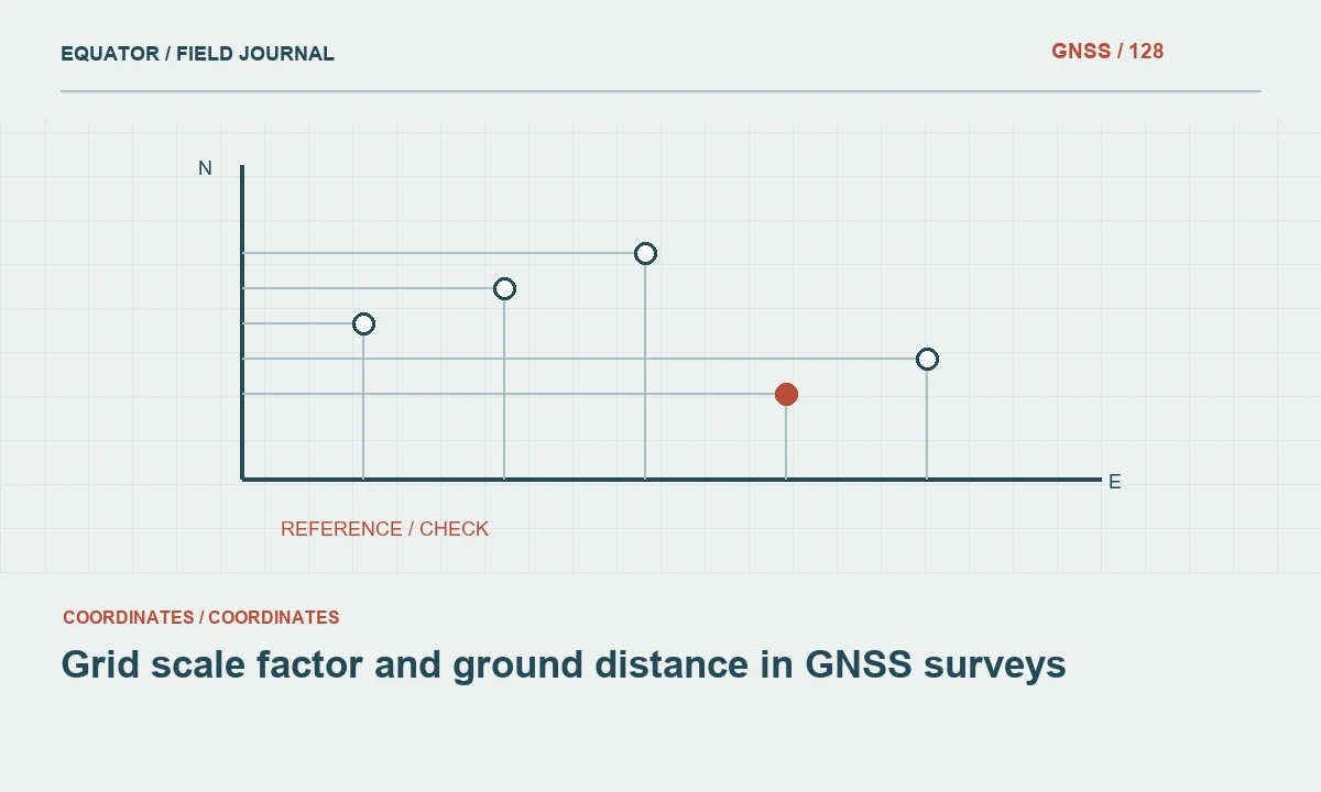
Identify which distance is being compared
A distance calculated between projected coordinates is a grid quantity. A field instrument may report a slope distance, a reduced horizontal distance or another processed value. These are not automatically identical. Before diagnosing a discrepancy, identify the physical and mathematical meaning of both numbers. A comparison is useful only when the quantities are defined consistently.
Agree the distance convention required by the project. Mapping, construction and control adjustment may use different representations for different purposes. The survey record should explain which values are stored and which are derived. Avoid treating every difference as an instrument problem or applying an unexplained scale factor merely because two displayed numbers are close.
Continue learning Grid vs ground distances: avoiding a layout mismatch
Separate projection and height effects
A map projection represents a curved reference surface on a plane, producing a location-dependent scale relationship. The relationship between ground and the reference ellipsoid also involves height. NOAA documentation distinguishes projection point scale, height factor and their combined effect. These concepts explain why a grid-to-ground comparison requires more information than a single generic map scale value.
Use the approved project method to calculate the relevant factors. Record which height type the method requires and avoid substituting an unrelated engineering elevation without checking the definition. The exact workflow depends on the reference and software. A formula copied without its conventions can produce a plausible but incorrect conversion.
Continue learning Defining a local survey grid: origin, orientation and external connection
Define factor direction explicitly
A factor may be described as grid-to-ground or ground-to-grid, and software labels are not always enough to establish how it is applied. State which input is multiplied or divided to obtain which output. Include a small worked project example with units and expected values. This is more reliable than handing over a number labelled scale with no operation definition.
Keep the factor’s source, location and assumptions. Do not assume the reciprocal has already been applied by the receiving tool. A controller, adjustment package and design drawing can each have their own settings. Test the complete workflow so the intended operation occurs once, rather than being omitted or applied twice.
Continue learning GNSS surveys across UTM zone boundaries
Assess variation across the project
Projection scale and height-related effects can vary with position and elevation. A constant project factor may be an approved approximation over a defined area, but its suitability should be assessed against the intended use. A factor selected near one control mark should not automatically be extended across a much larger or more varied project.
Review representative locations and the project’s distance requirements with the responsible survey role. Document the area and conditions for which the convention is adopted. If another grid or projection is chosen to manage distortion, preserve its complete definition. The aim is a coherent reference strategy, not a universal claim that one factor makes all coordinate distances equal to all ground measurements.
Continue learning Documenting coordinate epoch in GNSS survey data
Keep scale operations separate from reference transformations
A distance reduction, a local grid scale and a datum transformation are different operations even when each changes coordinate values. Record their sequence and purpose. Applying a scale about an unspecified origin can alter positions as well as distances. Do not use a generic drawing scale command as a substitute for a defined survey coordinate operation.
Preserve the source coordinates and approved transformation parameters. Test known points and distances after conversion. If a local ground-oriented grid is delivered, label it clearly and provide its relationship to the external reference. Similar-looking eastings and northings should not encourage users to treat it as an unchanged standard projected CRS.
Continue learning Grid vs ground distances: avoiding a layout mismatch
Configure instruments and design tools consistently
Prepare a controlled setup describing units, projection, factor convention, origin and height handling. Test it in the actual controller and receiving design software. Compare both point coordinates and a few representative distances. A setup that matches one origin point may still use an incorrect scale or orientation elsewhere.
Document software settings that automatically reduce or scale observations. Avoid adding a manual factor on top of an operation already performed by the equipment. Use a repeatable test dataset after configuration changes. This helps distinguish a genuine reference relationship from a mismatch introduced by the way a particular application presents or stores values.
Continue learning Defining a local survey grid: origin, orientation and external connection
Investigate discrepancies through the full chain
When distances disagree, check units, point identity, coordinate reference, height convention and applied factors before changing control. Determine whether one value is slope, horizontal ground, ellipsoidal or grid distance. A mismatch in quantity definition can look like a consistent scale error. The remedy should address that cause rather than force the numbers to match through an arbitrary adjustment.
Inspect the pattern across several lines of different lengths and locations. Keep original observations and calculations. If a correction is approved, record its basis and affected products. A single favourable comparison does not establish the whole workflow, especially when the project spans significant variation in position or elevation.
Continue learning GNSS surveys across UTM zone boundaries
Deliver a usable distance convention
Provide the reference definition, factor source, direction of application, relevant height assumptions and area of use. Include example calculations and independent checks. State which delivered coordinates are grid values and which, if any, belong to a local ground-oriented system. This prevents later teams from applying another conversion to data that already include the intended operation.
Archive configuration versions and the checks used for release. Reassess the convention if the project extent or requirements change. Reliable GNSS distance handling comes from clear definitions and tested operations. The important result is not a factor with many decimal places, but agreement on what each distance means and how the project moves between representations.
Continue learning Documenting coordinate epoch in GNSS survey data
Resolve a double-scaling example
Suppose a contractor imports a local project dataset and applies a grid-to-ground setting because the coordinate values resemble ordinary projected coordinates. The survey export may already include the approved local scale relationship. Compare the delivered reference note, controller settings and a known test line before modifying any geometry. The apparent discrepancy may come from applying the same intended operation twice.
Restore a controlled configuration and test several known points and distances. Keep the source release unchanged, and document which derived files were affected. A clear example in the handover note can prevent recurrence. This is why a local coordinate file needs an explicit distance convention and operation history even when its values look familiar to an experienced field crew.
If several contractors use different software, ask each to run the same controlled test dataset and return the relevant settings and results. Compare the operation direction and origin rather than only the final distance. A mismatch may appear in coordinates even when one selected line happens to agree. Record the accepted configuration for each system as part of the project reference package. This coordinated test helps prevent a distance convention from drifting into separate undocumented implementations across field crews and design teams.
Continue learning Grid vs ground distances: avoiding a layout mismatch
Practical checklist
- Identify grid, ground, horizontal and slope quantities separately.
- State factor direction and whether it has already been applied.
- Test coordinates and distances across the intended project area.
Plan your GNSS setup
Compare the EQ10 and EQ20 receiver specifications, then discuss the configuration and support your project needs.
Compare GNSS receivers