Defining a local survey grid: origin, orientation and external connection
Make a local engineering grid reproducible by documenting its full relationship to the project’s external coordinate and height references.
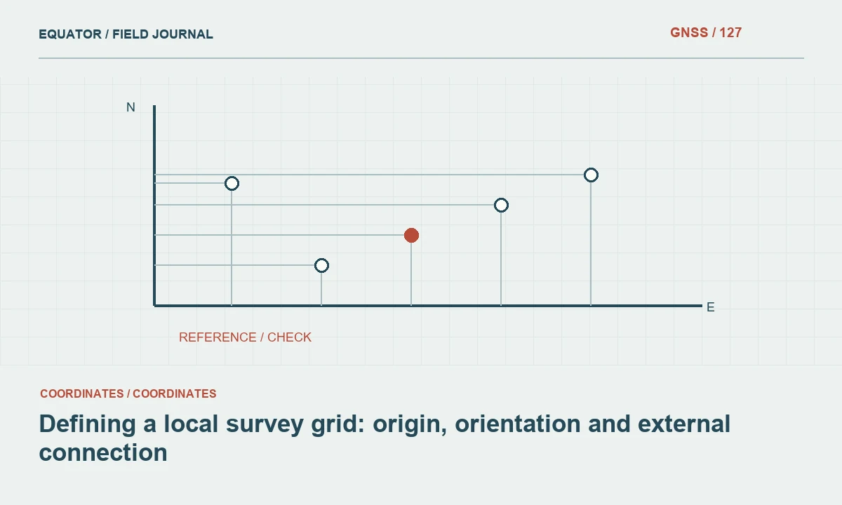
Define why the local grid is needed
A local grid can simplify construction coordinates, align axes with a site or support an engineering distance convention. State the purpose before choosing numbers for the origin. A convenient coordinate appearance is not a complete reference definition. The grid must remain connected to the survey evidence and understandable to future teams working outside the original site context.
Identify the responsible role that approves the grid and its intended area of use. A small site grid should not automatically be extended to a much larger corridor. Consider GIS exchange, design software and controller support. The best definition is one that meets the project’s needs and can be reproduced consistently, rather than one that depends on undocumented settings in a single field device.
Continue learning Grid vs ground distances: avoiding a layout mismatch
Specify the origin and axes unambiguously
Record the physical or mathematical origin, its coordinates in the external reference and its assigned local values. Define axis directions and units. An instruction such as north along the road is insufficient without a reproducible orientation reference. Include how rotation is measured and which direction convention the transformation uses.
Keep the origin definition separate from a temporary control mark that may later be damaged. If the grid is defined through several control points or a transformation, preserve the complete method and approved parameters. A single point can define a translation but does not by itself establish orientation and scale. The documentation should describe the actual relationship being used.
Continue learning Grid scale factor and ground distance in GNSS surveys
Document scale and distance conventions
Clarify whether local coordinate distances are intended to approximate ground distances or follow another defined grid convention. Record any scale operation, its direction and the point about which it is applied. Do not use the phrase ground coordinates as though it fully defines a mathematical system. The relationship must be explicit enough for another operator to reproduce.
Assess how the chosen approach behaves across the project extent and elevation range. A constant factor may be an approximation whose suitability depends on the task and area. Use the approved survey method and acceptance requirements. Avoid applying additional scale settings in design software if the controller or transformation has already incorporated the intended operation.
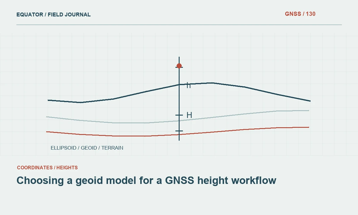
Continue learning Choosing a geoid model for a GNSS height workflow
Keep the height reference independent and clear
A local horizontal grid does not automatically define a vertical datum. State whether elevations come from a project benchmark, an official height system or another approved reference. Document the GNSS-to-height workflow, including geoid or vertical transformation models where used. An arbitrary local level should not be presented as a national datum elevation without a valid connection.
Test suitable benchmarks and preserve their identity and status. If the project applies a local vertical adjustment, record its basis and limits. Keep original ellipsoidal heights where relevant to the observation archive. Clear separation between horizontal grid definition and vertical reference prevents a correct plan position from concealing an incompatible construction level.
Continue learning Connecting PPP coordinates to local survey control
Establish the relationship with suitable control
Use control distributed appropriately for the transformation and project geometry. Check point identity, stability and observation quality before using coordinates to define the grid. A transformation can fit poor or misidentified control closely while remaining wrong. Preserve the observations, parameter estimation method and residual assessment through the approved project process.
Reserve independent points to test the relationship outside the defining set. Inspect differences across the site, not only near the origin. A scale or rotation issue can be small locally and grow with distance. Document excluded points and reasons. The result should be a tested spatial relationship, not merely a set of parameters that produces a visually pleasing overlay.
Continue learning Grid vs ground distances: avoiding a layout mismatch
Configure field and office systems consistently
Prepare a controlled configuration for controllers, GIS and design tools. Include the grid definition, units, height settings and approved control release. Test representative known points through each system’s actual import workflow. Different software may use different rotation signs, axis conventions or scale directions, so parameter names alone are not sufficient evidence of equivalence.
Keep a simple test dataset with expected local and external coordinates. Use it after configuration changes or new software setup. Avoid allowing each team to recreate the grid independently from a short verbal description. One documented definition and repeatable tests reduce the risk of several almost-compatible local grids developing within the same project.
Continue learning Grid scale factor and ground distance in GNSS surveys
Manage grid revisions as controlled changes
If control improvements require a revised transformation, record the reason, approval and affected area. Preserve the previous definition and identify which surveys used it. Do not overwrite parameters silently. A later user may need to interpret an older drawing in its original grid release rather than assume it follows the current configuration.
Distribute revised point, line and surface products coherently. Identify superseded files and remove them from active field folders while retaining the archive. Recheck the new release in the relevant equipment. A grid revision is an information change across the project, not only a numerical edit in a controller configuration screen.
Continue learning Choosing a geoid model for a GNSS height workflow
Deliver a complete local grid definition
Provide origin, axes, units, orientation, scale convention, external reference, height definition and transformation history. Include control schedules, independent checks and an example conversion. State the intended area and use limitations. A recipient should be able to reproduce the relationship without access to the original surveyor’s personal settings.
Archive the approved configuration and test data with the survey release. Future work should connect through the documented grid rather than infer it from a handful of coordinates. A dependable local grid is a defined and tested coordinate reference arrangement. Its simplicity for daily construction use should be supported by precise documentation behind the scenes.
Continue learning Connecting PPP coordinates to local survey control
Test a rotation-sign misunderstanding
Suppose a new controller matches the grid origin but its positions diverge as the crew moves across the site. Compare the orientation convention, axis order and scale settings with the approved definition. Matching one point verifies only part of the relationship. A rotation sign interpreted differently by two systems can create a pattern that is small near the origin and larger farther away.
Use the controlled test dataset to identify the mismatch and correct the configuration, preserving the original setup for the issue record. Recheck distributed independent points before production. Do not compensate by editing each control coordinate. The goal is one reproducible grid relationship shared by all systems, rather than a collection of local fixes that happen to agree near selected marks.
Store the corrected controller configuration with its software version and test results. A later device replacement should use this controlled package rather than recreate parameters from a screenshot. Include at least one test point far enough from the origin to expose orientation or scale behaviour within the intended project area. Keep the test coordinate definitions and expected outputs stable across releases unless the approved grid changes. This provides a practical verification tool that remains useful after the original configuration issue has been forgotten.
Continue learning Grid vs ground distances: avoiding a layout mismatch
Practical checklist
- Document origin, axes, orientation and scale completely.
- Define the vertical reference separately from the horizontal grid.
- Test distributed independent points in every receiving system.
Plan your GNSS setup
Compare the EQ10 and EQ20 receiver specifications, then discuss the configuration and support your project needs.
Compare GNSS receivers