Measuring near glass and metal facades with GNSS
Recognize reflections and obstructed geometry near buildings, then choose a checked method for the feature being surveyed.
Begin with the building environment
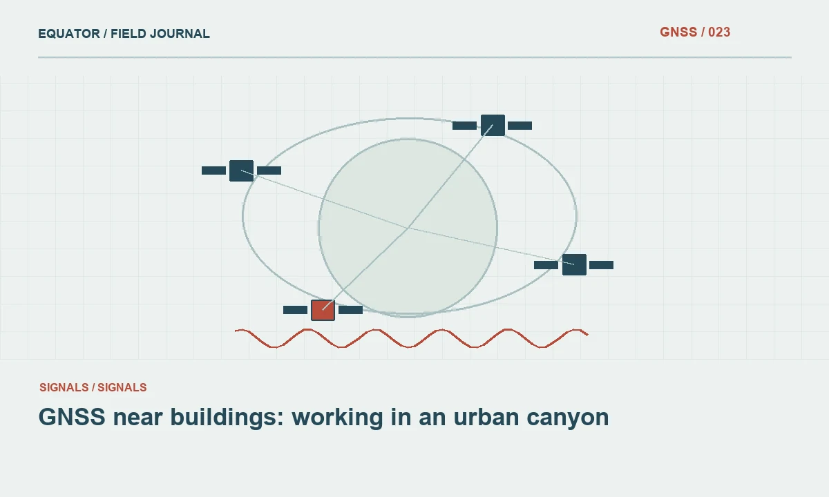
Glass, metal and other nearby surfaces can reflect satellite signals, while the building itself blocks parts of the sky. The resulting observation environment differs from an open field even when the receiver displays many satellites. Inspect the point, facade and surrounding structures before choosing a direct GNSS occupation. A short distance from a wall is not a universal boundary between good and bad observations because geometry and materials vary.
Define the physical feature precisely. A facade survey may need a corner, a wall face, a doorway reference or an asset attached to the building. The coordinate must describe the intended feature, not merely the nearest place where the rover can stand. This definition guides whether a direct occupation, a checked offset or another approved measurement method is appropriate and prevents an operational convenience from silently changing the object being surveyed.
Continue learning GNSS near buildings: working in an urban canyon
Distinguish reflections from other problems
Local multipath and obstructions affect satellite observations, while a lost correction link affects data delivery. Both can occur beside a building. Inspect correction age, solution state and available diagnostics together. If corrections remain timely but coordinates behave inconsistently near one facade, the local observation environment deserves investigation. The pattern is a clue, not proof of one unique mechanism, so preserve the evidence and avoid an unsupported diagnosis.
Check the reference configuration as well. A common offset at open control points should not be blamed on the wall simply because the current feature is difficult. Verify the system at a suitable open location before entering the building edge work. This establishes a comparison and helps the crew separate a project reference problem from an environment dependent observation problem that appears only near certain features.
Continue learning Planning GNSS observations under tree canopy
Observe behaviour through time
Watch coordinate stability and solution transitions during the occupation rather than reading one instant of the display. Repeated fixed and float changes, sudden height differences or disagreement between occupations require attention. A stable label alone is not an external validation. Preserve individual observations with times and notes so the office can compare the sequence with environmental conditions and any deliberate reinitialization.
Do not collect repeated points until one falls near the expected wall and then discard the others without explanation. That procedure selects a plausible answer rather than establishing a defensible measurement. If repeats are required, define how they will be evaluated before observing them. Keep the failed attempts and explain the acceptance or rejection decision. The record should show why the adopted coordinate is supported, not merely why it looks reasonable on a map.
Continue learning Planning GNSS surveys along urban streets
Use suitable nearby control
Identify open positions from which the target can be connected through an approved method. The control should have adequate geometry for the intended connection and be tied to the project reference. A nearby point is not automatically useful if the wall feature remains ambiguous or the offset cannot be measured reliably. Plan the connection and its checks rather than treating it as an informal adjustment made after GNSS becomes frustrating.
Preserve the control observations and the measurements to the feature. Record orientation, distances and point definitions as required by the chosen method. If specialized visual or laser assisted equipment is used, follow its documented initialization and operating conditions. Verify the result against appropriate checks. A feature that is convenient to reach through an assisted workflow still needs evidence that the recorded coordinate represents the intended physical location.
Continue learning Designing a GNSS ground control point layout for drone mapping
Keep antenna geometry under control
Avoid leaning the pole toward or against the facade to reach a difficult point unless an approved measurement mode and procedure support that geometry. A conventional vertical pole assumption does not describe a tilted antenna. Record the active observation mode and its required checks. The physical relationship between tip and antenna remains part of the measurement even when satellite processing appears satisfactory.
Keep the antenna clear of improvised supports and nearby equipment where practical. A metal railing, vehicle or temporary cover can alter the local environment. Do not solve a handling problem by creating an untested antenna arrangement and then assume it is equivalent to the open site configuration. If the point cannot be occupied under the approved geometry, use the planned alternative rather than concealing a change in method inside the same point code.
Continue learning GNSS near buildings: working in an urban canyon
Document the facade and feature
Take photographs that identify the exact target and show the nearby reflective and obstructing surfaces. Include the direction of the view or a sketch where useful. A close photograph of a corner helps define the target, while a wider view explains the observation environment. Link both to the point and occupation identifiers so later reviewers do not have to infer the relationship from an unordered image folder.
Record any offset or inaccessible contact clearly. A coordinate on an adjacent pavement point should not be labelled as the building corner unless the measured connection is preserved. If the final point is derived, identify it as such and keep its source observations. This is particularly important when a client compares the dataset with a facade model or another survey that uses a different convention for corners, surfaces or projecting elements.
Continue learning Planning GNSS observations under tree canopy
Review acceptance locally
Evaluate building edge observations as a distinct work group where the environment differs materially from open ground. Compare independent checks and repeated occupations without allowing a project wide average to conceal isolated failures. If a particular facade repeatedly defeats the direct method, allocate another method for that area. The decision should follow the evidence rather than an assumption that the same receiver must work equally well everywhere.
Keep unresolved features visible in the status register. A missing or provisional point is preferable to an unexplained accepted coordinate that later guides design in the wrong location. If additional work resolves the issue, preserve the original record and the final method. The resulting history helps another crew understand why neighbouring features may have different observation records even though they appear together in one final drawing.
Continue learning Planning GNSS surveys along urban streets
Use the result to improve future planning
Map difficult facade zones and note which approaches were successfully verified. That record can improve equipment allocation and production estimates for a return visit. Avoid converting one successful assisted observation into a blanket claim for all building materials and geometries. The useful lesson is specific: a documented method worked for a defined feature under observed conditions and passed the required checks.
For a hypothetical corner beside a glass curtain wall, open control and a checked terrestrial connection may provide a clearer result than repeated direct GNSS attempts. The final metadata should make that method visible. Reliable work near facades combines environmental judgement, physical point definition and independent evidence. It uses receiver diagnostics as part of the decision while retaining a practical route when the local observations cannot support the required coordinate.
Continue learning Designing a GNSS ground control point layout for drone mapping
Practical checklist
- Define the exact facade feature and inspect the local environment.
- Preserve repeated observations instead of selecting a plausible result.
- Use checked control connections when direct occupations are unsuitable.
Plan your GNSS setup
Compare the EQ10 and EQ20 receiver specifications, then discuss the configuration and support your project needs.
Compare GNSS receivers