Designing a GNSS ground control point layout for drone mapping
Distribute ground control around the project geometry and terrain, then reserve separate observations to test the finished photogrammetric result.
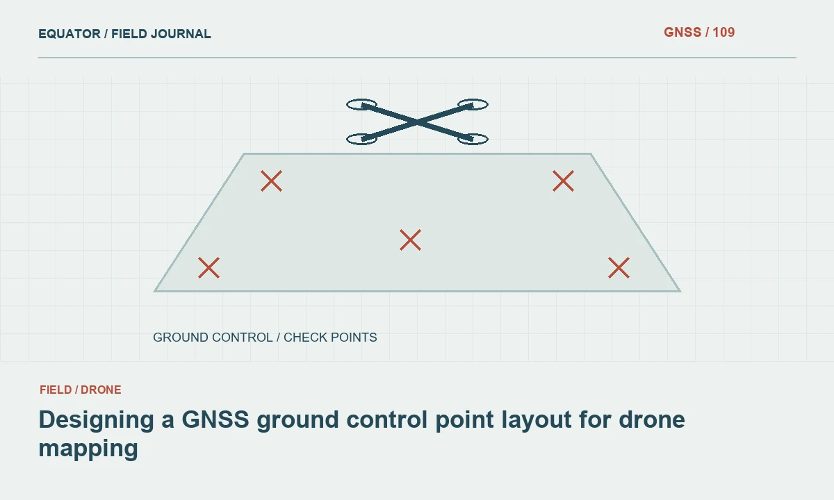
Begin with the mapping product and project shape
A ground control layout should follow the intended mapping product, terrain and image block geometry. An orthomosaic, surface model and detailed three-dimensional reconstruction may place different demands on the survey. Agree the output reference and assessment method with the processing team before placing targets. A fixed number of points copied from another project is not a substitute for this planning.
Review the project footprint, height changes, obstructions and access. Long narrow corridors behave differently from compact blocks, while steep terrain creates additional geometric challenges. Identify where control can be observed reliably and seen clearly in the photographs. The layout must work for both the ground survey and the image measurements that connect it to the photogrammetric model.
Continue learning Ground control points vs checkpoints for drone mapping
Keep control and checkpoints independent
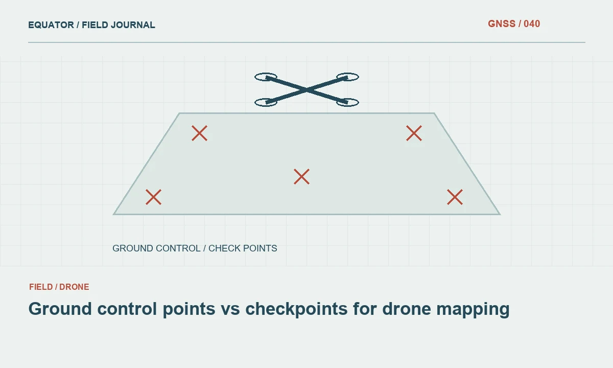
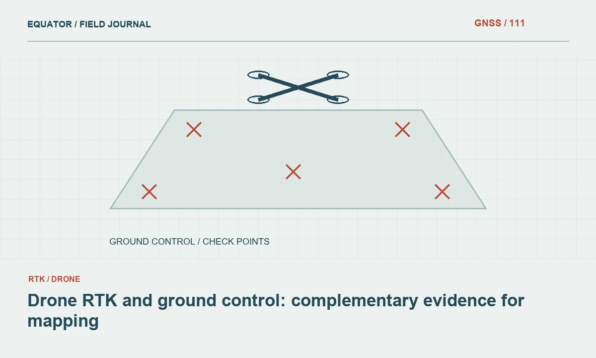
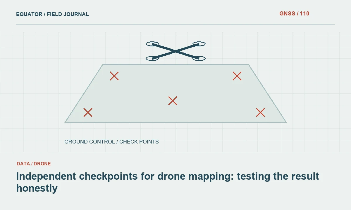
Ground control points contribute to the model adjustment. Checkpoints are reserved to evaluate the resulting product and should not be used to tune the solution they are testing. Plan both sets before fieldwork and identify their roles clearly. A point cannot provide an independent test if its coordinates were also used to constrain the same adjustment.
Use suitable checkpoint distribution across the project, including relevant terrain and surface conditions. Avoid placing all checks beside a convenient access road while the main product covers a different environment. The assessment should reflect the intended use and project specification. Report the control and checkpoint roles with the final dataset so another reviewer can understand which evidence supports calibration and which tests performance.
Continue learning Drone RTK and ground control: complementary evidence for mapping
Distribute control through the image block
Place control so that it constrains the project’s horizontal extent and elevation variation. Avoid a layout concentrated only in one corner or on one flat surface when the model covers a much larger and more varied area. Review likely image overlap and target visibility. A point outside usable imagery contributes little even if its GNSS coordinate is well measured.
Consider internal coverage as well as the perimeter, especially where terrain or block geometry changes. The exact layout should follow the processing method and project requirements rather than a universal diagram. Discuss inaccessible areas with the processing team before flying. A planned alternative is preferable to discovering after collection that the only control for a critical area is hidden beneath vegetation or shadow.
Continue learning Independent checkpoints for drone mapping: testing the result honestly
Design targets that can be identified consistently
Choose target size, contrast and placement for the planned image resolution and surface conditions. The centre used by the ground crew must be the same centre identified in the imagery. Secure targets so they do not move between the GNSS observation and the flight. Record identifiers visibly and keep a target schedule with photographs.
Avoid placing targets on unstable material or locations likely to be disturbed by vehicles or operations. Inspect them before and after the relevant collection window where practical. If a target moves, record the event and do not combine its earlier coordinate with later imagery as though nothing changed. A clear target identity is as important as the precision of its position.
Continue learning GNSS floodplain elevation mapping: control, terrain and vertical checks
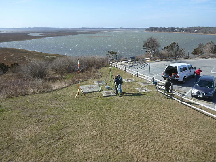
Survey each target in the approved reference
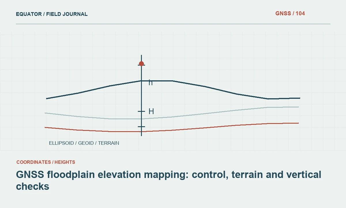
Confirm the horizontal reference, vertical reference, units and coordinate epoch where relevant. Record antenna reference point and height conventions consistently. If orthometric or another engineering elevation is required, document the geoid or vertical operation. An ellipsoidal height column should not be relabelled as a different height type without an actual approved conversion.
Observe control checks and repeat selected target measurements with meaningful independence. Evaluate the GNSS environment at each target, especially near trees, structures or reflective surfaces. A fixed RTK status supports the assessment but does not prove that every observation is correct. Preserve raw data where available and maintain a traceable link between target identifier, coordinate and observation record.
Continue learning Ground control points vs checkpoints for drone mapping
Coordinate field and flight timing
Plan the ground survey and aerial collection so that targets represent the same physical locations. Active construction, farming or material handling can alter the scene between visits. Record observation dates and flight dates, and note any target disturbance. A model can be internally consistent with images while disagreeing with a target coordinate measured after the target moved.
Provide the flight team with the target schedule and coverage plan. Confirm that every required target appears in enough suitable images for the intended processing workflow. Review image sharpness and target visibility before demobilising where practical. A short field review can prevent a complete return flight when one critical target was obscured or omitted.
Continue learning Drone RTK and ground control: complementary evidence for mapping
Check image marking and adjustment behaviour
During processing, inspect target identification in each relevant image. A wrongly marked centre or mismatched identifier can undermine otherwise good ground observations. Review residual patterns and any points excluded from the adjustment. Do not remove a difficult point merely to improve a summary statistic without investigating the reason for its disagreement.
Keep the adjustment settings and control weighting consistent with the project’s method. Compare independent checkpoints against the released product, using compatible reference and height definitions. Assess spatial patterns rather than only a single overall value. A block can fit its control well while showing distortion elsewhere, which is why independent distributed checks are necessary.
Continue learning Independent checkpoints for drone mapping: testing the result honestly
Deliver control evidence with the drone products
Provide the target schedule, coordinates, reference definitions, observation methods and checkpoint assessment. Identify which points were used as control, held as checks or excluded, and explain exclusions. Include photographs and relevant target stability notes. This allows the recipient to understand the evidence behind the orthomosaic or surface model rather than receiving only a processing report.
Archive raw survey data where available, flight records and the processing version used for release. If the model is revised, preserve the earlier product and assessment. A dependable drone ground control layout is a planned relationship between the ground survey, image geometry and independent validation. Its value comes from how these elements work together, not simply from the number of targets placed.
Continue learning GNSS floodplain elevation mapping: control, terrain and vertical checks
Test a corridor layout before the main flight
For a long narrow road project, review how control and checks cover both ends, intermediate sections and meaningful elevation changes. Points clustered around the launch site may be convenient to survey but provide weak evidence about the far end. Walk through the layout with the processing team and identify which observations constrain each part of the image block.
Create a small pilot block if the terrain or method is unfamiliar. Survey, fly, process and assess it using the intended production workflow. Use the findings to revise target placement, visibility and checks before the full campaign. Keep the pilot evidence in the project record. This practical test can reveal a target identification or reference problem that a theoretical point-count rule would never expose.
After the pilot, record which observations were used as control and which remained independent. Keep the target photographs and flight coverage together so the reason for any layout change is understandable. A failed pilot target may reveal a visibility problem rather than a survey problem, and the remedy should address that cause. The production plan should identify the revised layout and checks explicitly. This prevents a useful trial from becoming an informal memory while later crews unknowingly return to the original untested arrangement.
Continue learning Ground control points vs checkpoints for drone mapping
Practical checklist
- Plan independent checkpoints before placing control.
- Match target visibility to the intended image resolution.
- Deliver target roles and reference definitions with the products.
Plan your GNSS setup
Compare the EQ10 and EQ20 receiver specifications, then discuss the configuration and support your project needs.
Compare GNSS receivers