Checking orthomosaic coordinate alignment against GNSS evidence
Investigate reference definitions, point identity and spatial patterns before shifting a drone orthomosaic to fit another map.
Define which datasets should agree
An orthomosaic can be compared with GNSS points, design drawings, existing imagery or a GIS basemap. These sources do not necessarily have the same reference, date or quality. Identify which dataset is the approved comparison evidence and what physical features should match. A visually familiar background image is not automatically a survey control source.
State whether the check concerns absolute position, alignment with a project grid or local feature consistency. Different questions require different evidence. A map can align locally with an older drawing while remaining incompatible with an external reference. The review should establish the intended relationship before anyone applies a translation or rotation to make the display look more convincing.
Continue learning Local site calibration: connecting GNSS to project coordinates
Verify reference definitions and transformations
Record the orthomosaic CRS and the source of its georeferencing. Compare this with the GNSS point reference, including datum realisation, coordinate epoch where relevant, units and local grid settings. Check whether any transformation was applied during processing or import. Similar labels can conceal different operations, while different labels may be connected correctly through an explicit transformation.
Distinguish assigning a CRS from transforming coordinates. Assignment tells software how existing values should be interpreted; transformation calculates values in another reference. Reassigning a label to force a match can create a misleading result. Preserve the original dataset and document the actual operation used to produce any corrected output.
Continue learning Choosing and checking control points for coordinate transformations
Check point and feature identity
Use clearly identifiable features that represent the same physical point in both datasets. A target centre is often less ambiguous than a vegetation edge or an indistinct road shoulder. Confirm that the GNSS observation and image refer to the same survey period. Construction, moving objects or displaced targets can create real differences unrelated to georeferencing.
Inspect the image at an appropriate scale and record how the comparison position was selected. Avoid choosing a nearby pixel simply because it reduces the residual. If a feature cannot be identified consistently, flag it as unsuitable for the check. An assessment based on ambiguous features can produce a precise-looking statistic without a well-defined physical comparison.
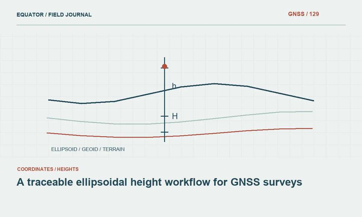
Continue learning A traceable ellipsoidal height workflow for GNSS surveys
Separate control residuals from independent checks
Points used to constrain the photogrammetric model show how that solution fits its inputs. Independent checkpoints test the released product without contributing to that fit. Keep these roles distinct in the report. A small control residual is not equivalent to a small independent position difference throughout the orthomosaic.
Review checkpoint distribution across the project. Checks concentrated near one corner may not expose distortion at the opposite edge. Include the conditions relevant to the product’s intended use. Preserve checkpoint coordinates, observation methods and reference metadata so an apparent alignment problem can be traced to the map, the check survey or an incompatibility between their definitions.
Continue learning Connecting PPP coordinates to local survey control
Interpret the spatial pattern of differences
Map the residual vectors and inspect their direction and magnitude across the footprint. A near-uniform shift suggests a different investigation from a rotation, scale trend or local distortion. Terrain, image coverage and distance from control may help explain the pattern. A single average difference can conceal these distinctions and lead to the wrong remedy.
Investigate reference settings, image positions, target marking and processing before editing the final raster. If only one checkpoint disagrees, confirm its identity and observation evidence. If all points show a systematic pattern, examine the whole reference chain. Do not remove or move points solely to produce a favourable summary; preserve the evidence and document the reasoning behind any exclusion.
Continue learning Local site calibration: connecting GNSS to project coordinates
Review resampling and raster metadata
When a raster is reprojected, record the source and target references, transformation operation, output resolution and resampling method. These choices affect the delivered grid and image appearance. Repeated resampling can change the representation of small features. Keep a suitable source product so later revisions do not depend on repeatedly transforming an already transformed copy.
Check the raster’s georeferencing metadata after export and reopen it in the receiving software. Confirm that sidecar files or embedded reference information are included as required by the format. A correctly processed image can appear misplaced if the recipient receives only part of its georeferencing package or interprets an incorrect reference assignment.
Continue learning Choosing and checking control points for coordinate transformations
Avoid cosmetic shifts without a cause
A final image translation may be appropriate in a documented workflow, but it should not be used to hide an unresolved reference or model problem. Explain what the operation corrects and which evidence supports it. Test the result with independent observations not used to estimate the adjustment. A visually improved fit near one feature can worsen the rest of the project.
Preserve the original orthomosaic, correction parameters and released version. If the issue originates in the photogrammetric model, reprocessing may be more appropriate than editing the raster alone. Related surface models and point clouds may otherwise remain in the old position. The correction strategy should keep all delivered products spatially coherent.
Continue learning A traceable ellipsoidal height workflow for GNSS surveys
Deliver an alignment assessment with the map
Provide reference definitions, comparison points, residuals, exclusions and the product version assessed. Explain any transformation or correction applied. Include limitations related to feature identity, observation dates or inaccessible areas. A recipient should be able to understand why the product is aligned appropriately without relying on a screenshot over a basemap.
Archive the original observations and processing records where available. Future updates should use the same documented reference chain or clearly state what changed. Reliable orthomosaic alignment is an evidence-based relationship between the image product and a defined spatial reference. It is not simply the appearance of agreement when two layers are displayed together.
Continue learning Connecting PPP coordinates to local survey control
Diagnose a basemap disagreement
Suppose the orthomosaic agrees with distributed GNSS checkpoints but appears offset from an online basemap. Review the basemap’s source, date and stated positional suitability before altering the survey product. The imagery may be older, differently referenced or less accurate for the project area. A familiar road shape does not make the basemap a superior control source.
Show the checkpoint evidence and retain the approved survey reference. If the client requires alignment to a particular non-survey background for presentation, treat that as a separate derived display product with an explicit purpose. Do not overwrite the surveyed release silently. This preserves a dependable engineering or GIS dataset while allowing the presentation requirement to be handled without confusing visual convenience with measured position.
For the presentation copy, use a distinct filename and metadata note identifying the display adjustment and its purpose. Keep it separate from the surveyed orthomosaic and any related elevation products. If the adjusted image is later requested for analysis, direct the user to the authoritative survey release and its reference evidence. This simple product distinction prevents a display convenience from becoming an undocumented coordinate convention. It also lets the project satisfy a communication need while preserving a coherent spatial foundation for technical work.
Continue learning Local site calibration: connecting GNSS to project coordinates
Practical checklist
- Compare defined physical features and compatible references.
- Inspect residual patterns across the whole image block.
- Preserve original rasters and document every correction.
Plan your GNSS setup
Compare the EQ10 and EQ20 receiver specifications, then discuss the configuration and support your project needs.
Compare GNSS receivers