Slant and vertical GNSS antenna heights explained
Record the measurement geometry correctly so software can reduce the antenna observation to the survey mark.
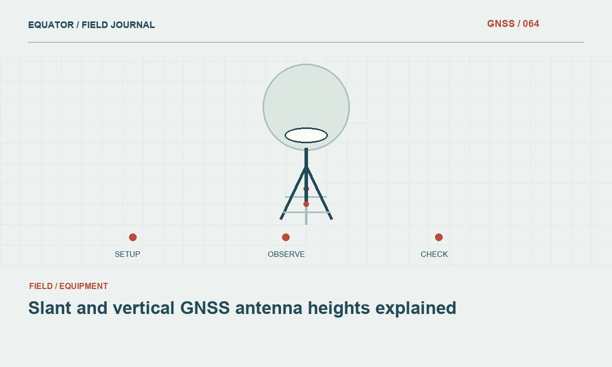
The two measurements describe different geometry
A vertical antenna height follows the vertical separation between the mark and the defined reference point. A slant height follows an inclined line from the mark to a specified measurement point on the antenna assembly. The values are not interchangeable. A slant measurement may be convenient on a tripod, but its interpretation depends on the geometry and the antenna model expected by the controller or processing software.
The purpose of the height entry is to connect the observed antenna position to the physical survey point. A mistake in that connection can affect all rover coordinates from a base session or every point measured with a wrongly configured pole. A fixed solution and a small internal estimate do not independently verify the height geometry. It needs its own physical inspection and a suitable coordinate check.
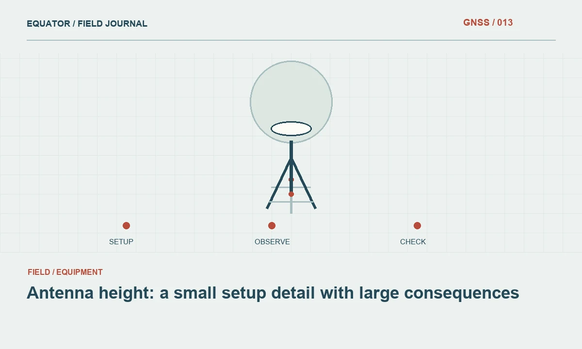
Continue learning Antenna height: a small setup detail with large consequences
Read the instrument diagram first
Find the documented measurement point for the exact antenna or integrated receiver. The diagram should explain whether the software expects a distance to the ARP, a height hook, an edge or another marked feature. Select the corresponding entry method in the job settings. Do not use a remembered convention from another receiver simply because both instruments are mounted on tripods.
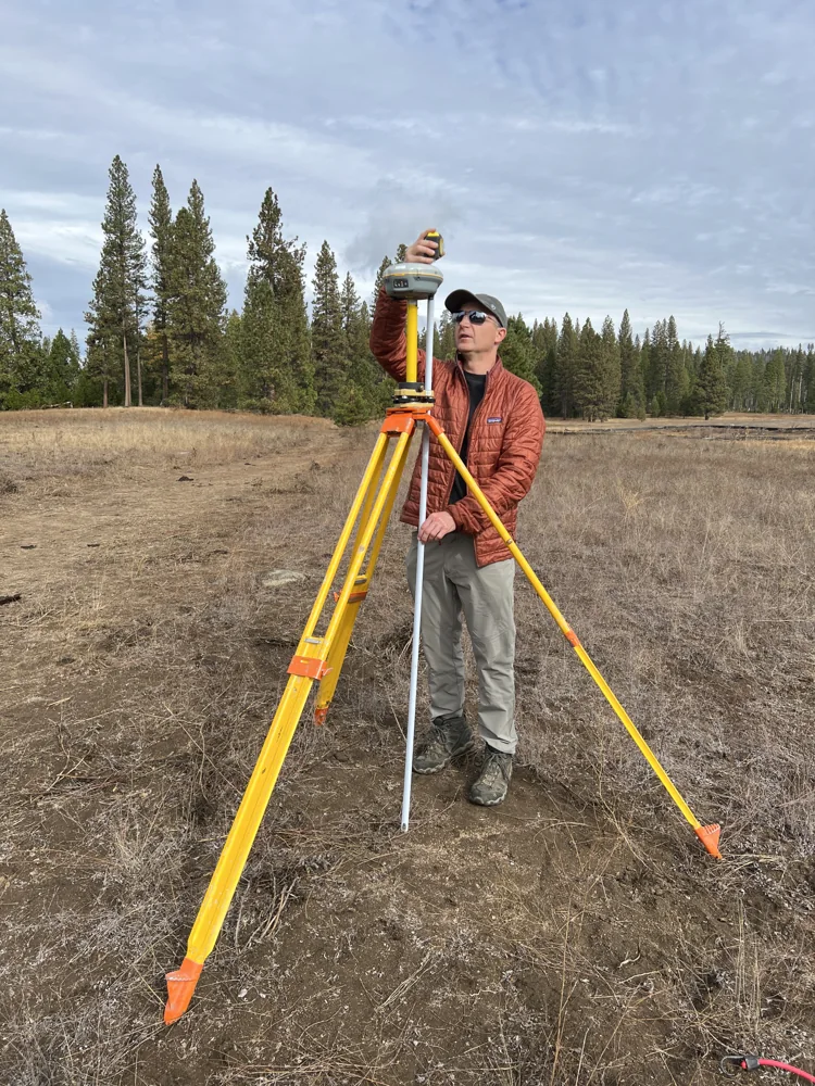
If the equipment includes a height measuring accessory, check how it is seated and how its reading is interpreted. A dedicated accessory can reduce ambiguity, but only when used in the intended way. Record the accessory or method in the field sheet. This gives an office reviewer the information needed to reproduce the reduction without asking the operator to reconstruct the setup from memory weeks later.
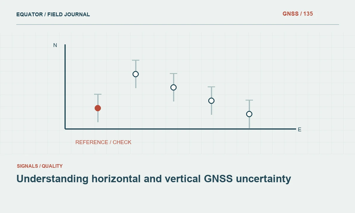
Continue learning Understanding horizontal and vertical GNSS uncertainty
Measure after the setup is stable
Complete centering and levelling, tighten the support and inspect it again before measuring height. A tripod adjustment made after the measurement can change the geometry. Keep the tape aligned with the intended points and avoid reading from an undefined part of the mark. Use a measurement tool appropriate for the required work and record units explicitly, including whether a displayed value is metres or another unit.
Take an independent confirmation where required by the procedure. For a slant method, measurements from appropriate positions can help reveal a setup inconsistency, provided the manufacturer method supports that approach. Do not improvise a geometric average without understanding the equipment convention. Preserve the actual readings and note any discrepancy that prompted a remeasurement so the final recorded value has a clear basis.
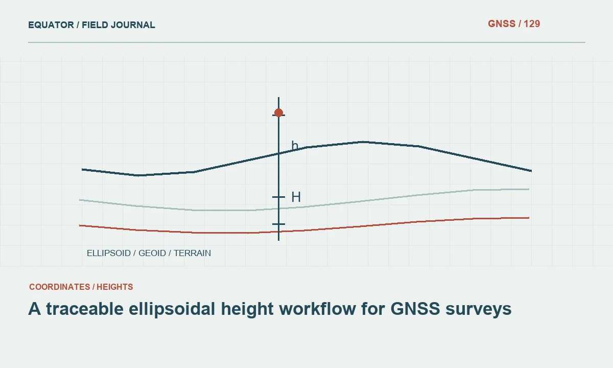
Continue learning A traceable ellipsoidal height workflow for GNSS surveys
Account for mounting components
Inspect the adapters, extensions and plates between the support and antenna. Their contribution may already be included in a documented measurement method or may require explicit treatment. Adding an offset twice is as problematic as omitting it. Draw a simple section of the setup when the component stack is unfamiliar and identify exactly where the tape begins and ends.
For a rover pole, verify that the entered pole height corresponds to the installed tip and antenna mount. Replacing a worn tip or adding an extension can change the relationship even if the pole scale has not moved. Use the equipment instructions to determine how the nominal length is defined. A number printed on the pole is a useful reference, but it is not a substitute for checking the actual assembly.
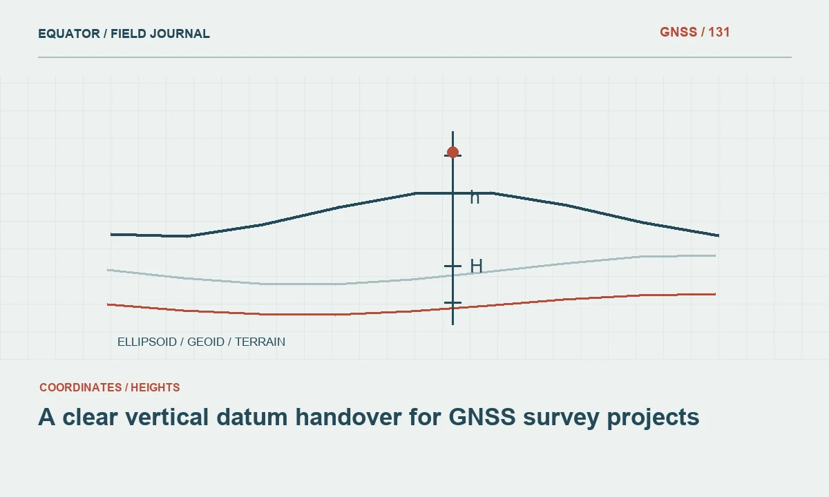
Continue learning A clear vertical datum handover for GNSS survey projects
Enter and confirm the height
Use the correct height field and measurement type in the controller. Read back the value and units before starting the base or collecting important points. If a job template supplies a default height, confirm it against today's setup. Defaults save time only when they match the physical configuration; otherwise they can reproduce the same mistake across many observations without attracting attention.
Record the raw reading separately from any reduced height displayed by software. Include antenna identification and the selected measurement method. This distinction is essential when data are later imported into another processing package. The second program may expect an ARP height rather than the original slant reading. Passing an unlabeled value between programs creates ambiguity that a careful field record could have prevented.
Continue learning Antenna height: a small setup detail with large consequences
Investigate a suspected height error
If checks show a persistent vertical discrepancy, compare the physical measurement with the controller entry before changing unrelated settings. Review the measurement type, units, antenna model and adapters. Then inspect the vertical coordinate reference and geoid model. Keeping those investigations separate helps avoid a situation where a reference conversion is altered to hide a physical height mistake.
Determine the affected interval. A wrong base height may influence an entire setup, while an incorrect rover pole height may begin at a particular equipment change. Preserve the observations and configuration history. Apply corrections only through an approved, documented method and verify the corrected result against independent checks. Do not overwrite the original height record merely to make it look as though the correct value had been used from the start.
Continue learning Understanding horizontal and vertical GNSS uncertainty
Make height practice consistent
Provide a short equipment specific instruction with a diagram, field names and an example of the recorded information. Use the actual hardware during training. Ask the operator to explain whether the distance is vertical or slant and which point the software will reduce it to. This practical demonstration is often more effective than repeating an abbreviation in a checklist.
Keep height records with setup identifiers and observation files. When a different antenna or adapter is introduced, update the instruction and repeat the relevant checks. Consistent height practice does not require complicated paperwork. It requires a clear physical definition, a matching software convention and enough preserved information for another person to reconstruct the relationship between the antenna observation and the mark coordinate.
Continue learning A traceable ellipsoidal height workflow for GNSS surveys
A handover example for height entries
Imagine a base setup measured by a slant method in the controller and later imported into a processing package that expects a vertical ARP height. The handover should include the original reading and the controller's documented reduction, not only an unlabeled number copied from a screen. The office can then select the appropriate input convention and verify that the antenna geometry is represented once, in the intended stage of processing.
If the receiving software cannot reproduce the original method directly, use an approved geometric reduction and preserve its calculation or output record. Do not enter the slant reading as though it were vertical simply because the numeric fields accept it. Test the result at suitable control and retain the software versions used. This example illustrates why clear labels are part of measurement quality: the same carefully observed distance can create a wrong point height when its meaning is lost between programs.
A useful field sheet shows the raw reading and selected method in adjacent fields. That arrangement makes a mismatch easier to notice during read back. Keep any software-calculated reduction separately labelled, so a reviewer can follow the original observation without mistaking a derived vertical value for the distance the operator actually measured.
Continue learning A clear vertical datum handover for GNSS survey projects
Practical checklist
- Match the raw measurement to the documented instrument method.
- Confirm adapters, units and software entry type.
- Preserve raw and reduced heights as distinct labelled values.
Plan your GNSS setup
Compare the EQ10 and EQ20 receiver specifications, then discuss the configuration and support your project needs.
Compare GNSS receivers