Understanding the GNSS antenna reference point
Keep the physical mark, antenna reference point and electrical phase centre distinct when measuring and processing GNSS heights.
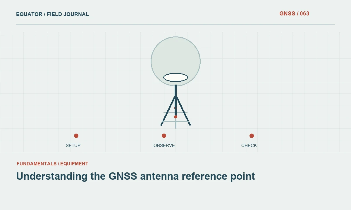
Separate three different locations
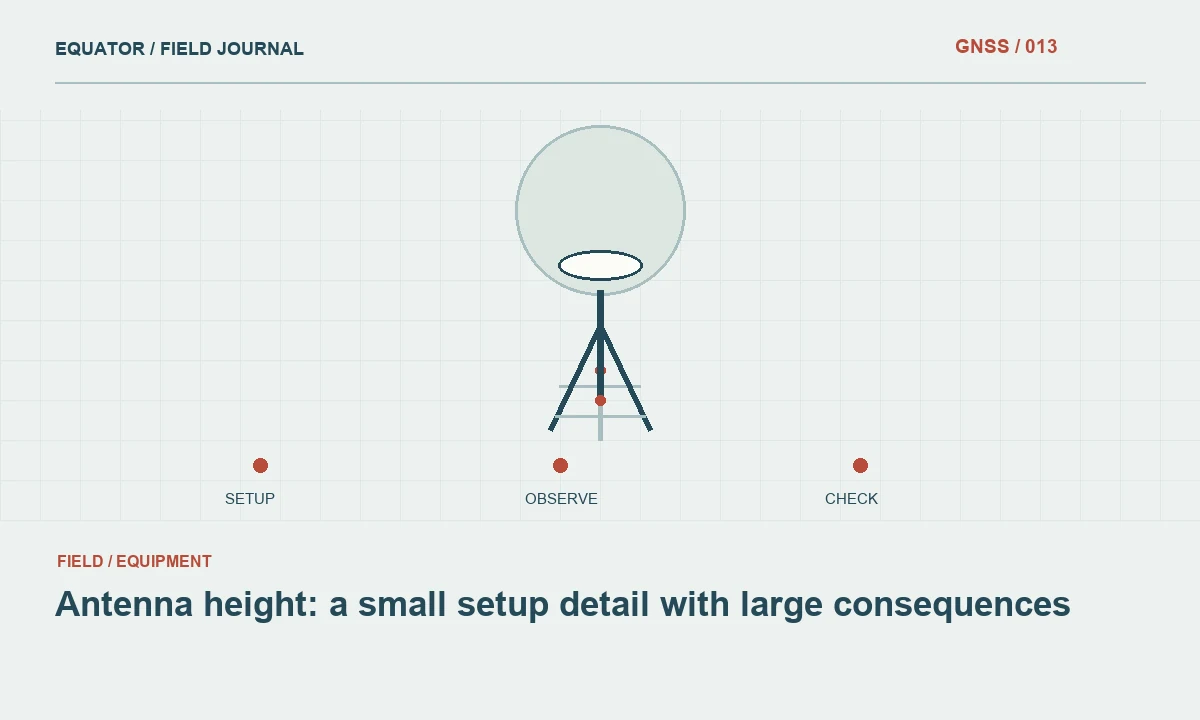
The ground mark, the antenna reference point and the electrical phase centre describe different parts of a GNSS measurement. The mark is the physical point whose coordinate the project needs. The antenna reference point, often abbreviated ARP, is a defined physical location on the antenna assembly. The electrical phase centre relates to how signals are observed and is represented through antenna models rather than a tape measurement to an imagined point inside the receiver.
Confusing these locations can create a systematic height error even when satellite tracking and ambiguity resolution are satisfactory. The controller or processing software needs an appropriate combination of antenna identification and measured geometry to reduce the observed antenna position to the mark. Learn the instrument's convention before taking a height measurement, especially when an integrated receiver and a separate antenna use different diagrams.
Continue learning Antenna height: a small setup detail with large consequences
Find the manufacturer definition
Use the antenna or receiver documentation to identify the ARP and the supported measurement points. Some equipment provides a dedicated height hook or a marked edge for slant measurements. Those convenient measurement points are not automatically the ARP itself. The software may apply a model specific geometric reduction when the corresponding method is selected. Record both the measured point and the entry method.
Keep a clear reference diagram in the crew instructions. A photograph of the equipment can supplement the manufacturer diagram, but should not replace its definition. If several antenna models are used, label the diagrams carefully. A measurement convention learned on one device should not be transferred to another simply because the housings look similar or share a familiar brand name.
Continue learning Using GNSS antenna calibration information correctly
Measure the connection to the mark
Centre the antenna over the defined mark and inspect the support before measuring height. Use the tape or measuring accessory in the intended way and record units. A vertical measurement and a slant measurement describe different geometry. Entering a slant distance into a vertical height field produces a predictable reduction mistake; additional satellite observations do not remove that mistake.
Preserve the raw height reading in the field record. If software calculates a reduced value, retain the method and antenna model needed to reproduce it. This allows an office reviewer to distinguish an incorrect reading from an incorrect reduction. A single unlabeled final height leaves that distinction unresolved and makes a later correction more speculative than it needs to be.
Continue learning A traceable ellipsoidal height workflow for GNSS surveys
Include adapters and offsets
Adapters, extensions and mounting plates can change the distance between the mark and the defined antenna reference point. Inspect the actual stack of equipment. A pole labelled with a nominal length may not represent the complete geometry if its tip, adapter or antenna mount has changed. Check the manufacturer guidance for the way those components are included in the height entry.
Where a deliberate horizontal eccentricity exists, document it explicitly and use an approved reduction method. Do not assume that all offsets are vertical merely because a conventional tripod setup usually is. Permanent station and high precision workflows can require detailed eccentricity records. The appropriate level of detail depends on the project, but every workflow benefits from stating what the measured distance actually represents.
Continue learning A daily GNSS base setup workflow for survey crews
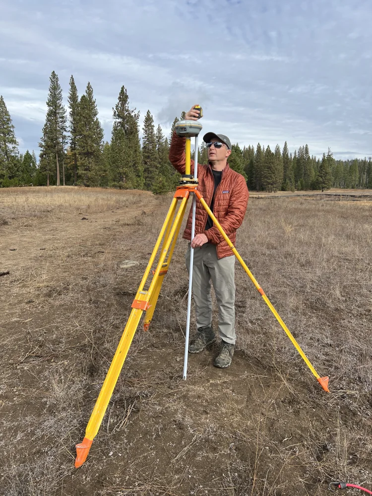
Select the correct antenna model
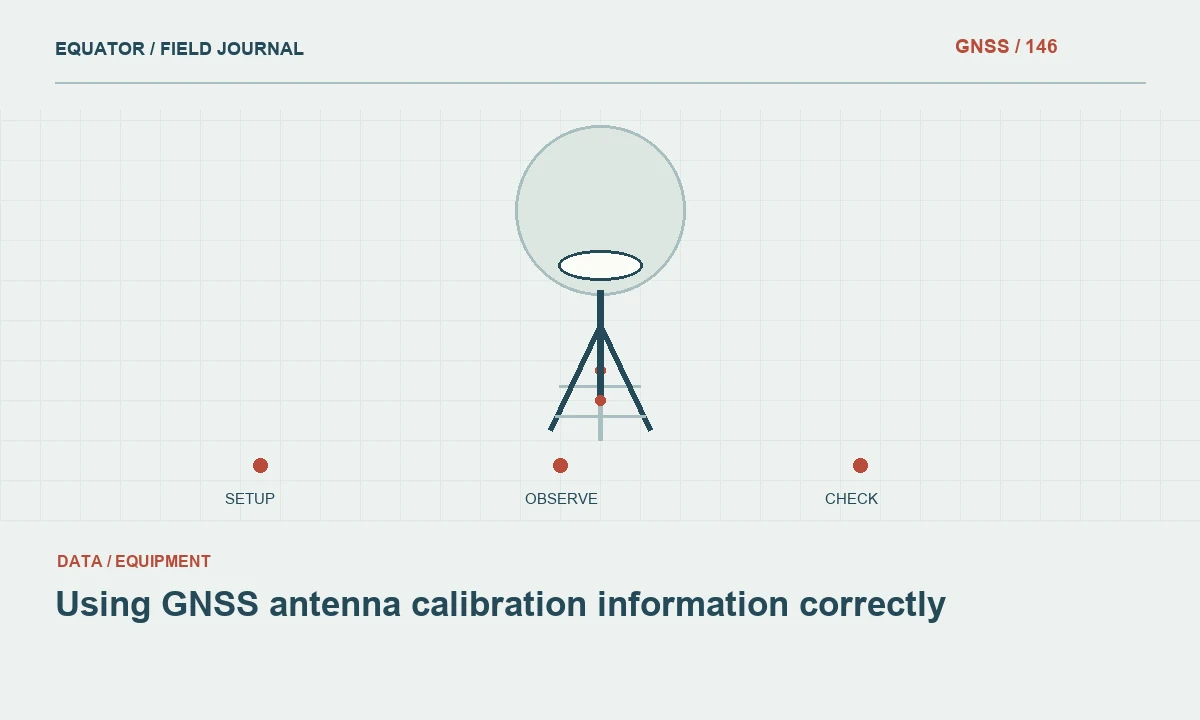
Processing models distinguish antenna types and, where applicable, radome combinations. Select the exact supported identification rather than the nearest looking name. The model describes electrical behaviour that a tape measurement cannot supply. Keep antenna serial numbers and configuration records when the workflow requires them, especially for reference stations or campaigns where equipment changes need to be traced across time.
Do not apply antenna corrections twice or omit them because a coordinate has already been exported through another program. Trace which software performs each reduction. A useful processing note lists the input height convention and the antenna model used at each stage. This is particularly helpful when raw data move between controller software, a conversion tool and a separate post processing package.
Continue learning Antenna height: a small setup detail with large consequences
Check the complete height chain
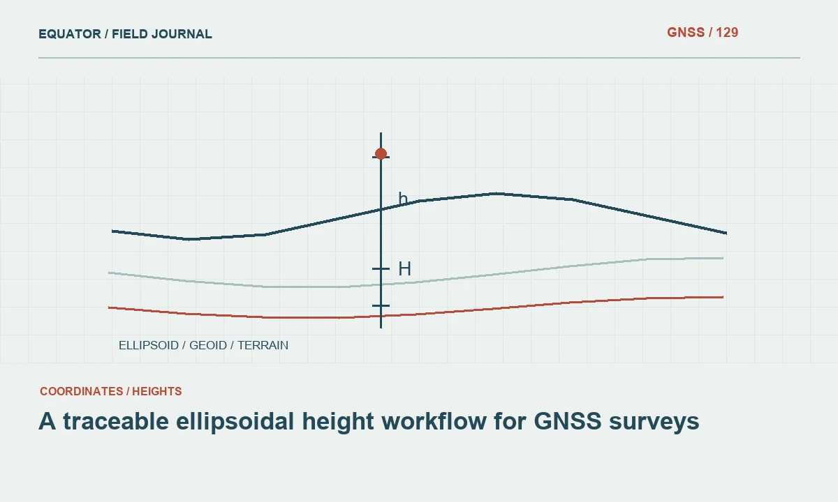
Use suitable known points to verify that the workflow produces the intended mark height. Confirm the height type as well as the antenna reduction. Ellipsoidal and orthometric heights are different coordinate quantities, and a geoid model belongs to that later reference conversion rather than the physical tape measurement. Drawing the chain from mark to antenna to delivered height often makes an otherwise confusing setup easier to review.
If a consistent vertical discrepancy appears, inspect antenna height entry, antenna model, adapters and vertical reference settings in a controlled order. Avoid changing the geoid selection simply to cancel a physical measurement error. A result that agrees at one point through two compensating mistakes may fail elsewhere or become impossible to reproduce when another operator uses the nominally same procedure.
Continue learning Using GNSS antenna calibration information correctly
Keep the definition with the data
Store the antenna identification, height measurement method, raw reading and setup date with the observation files. For repeated setups, make a separate record for each occupation. A receiver model name in the equipment inventory is useful, but it does not tell a reviewer which height hook, adapter or measurement convention was used on a particular morning.
Train the crew using the actual equipment rather than only a written abbreviation. Ask operators to identify the mark, ARP and measured point physically, then explain how the controller interprets the entry. Understanding that geometry prevents a class of errors that can otherwise survive excellent GNSS observations. The objective is a reproducible relationship between the signal measurement and the physical point the client expects the coordinate to describe.
Continue learning A traceable ellipsoidal height workflow for GNSS surveys
An office review of the antenna chain
When reviewing an unfamiliar dataset, ask for the antenna model, measured point, raw reading, entry method and adapters. Sketch the physical chain before interpreting the exported height. If those items are available, the reviewer can determine whether the software received a slant measurement, an ARP height or a value already reduced elsewhere. If they are missing, the uncertainty should be recorded rather than filled with an assumption based on the receiver name.
Keep antenna reduction separate from the later conversion between ellipsoidal and orthometric height. They answer different questions: one connects the signal observation to a physical mark, while the other expresses that mark in a chosen vertical reference. A useful review follows both steps in order and identifies the software responsible for each. This prevents a convenient numerical agreement produced by two compensating mistakes from being mistaken for a reproducible and correctly defined height workflow.
When an antenna name is abbreviated in a controller list, retain the full documented identification in the equipment record. Similar labels can conceal different antenna or radome combinations. The analyst should be able to resolve the selected entry without guessing from housing colour or a partial name remembered by an operator after the campaign.
Continue learning A daily GNSS base setup workflow for survey crews
Practical checklist
- Identify the physical ARP using the correct equipment diagram.
- Record raw height, measurement method, units and adapters.
- Verify antenna reductions separately from geoid and datum settings.
Plan your GNSS setup
Compare the EQ10 and EQ20 receiver specifications, then discuss the configuration and support your project needs.
Compare GNSS receivers