Understanding horizontal and vertical GNSS uncertainty
Horizontal precision, vertical precision and height reference information answer different questions when a GNSS result is reviewed.
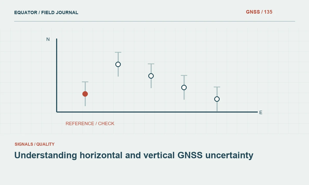
Read the uncertainty label before the number
A GNSS controller may display horizontal precision, vertical precision, estimated accuracy or a coordinate standard deviation. These labels are not interchangeable across every receiver and software package. Begin by identifying the manufacturer's definition and the confidence convention used for the displayed value. A number without that context cannot be compared fairly with a project requirement or a discrepancy measured against an independent control point.
Horizontal uncertainty describes behavior in a plane, while vertical uncertainty concerns the height component. The geometry of satellite observations and the processing model affect these components differently. Do not assume that a successful horizontal check proves the elevations are suitable for a task. A utility inventory can tolerate a height uncertainty that would be unacceptable for drainage design, so evaluate each component against its actual intended use.
Continue learning Accuracy, precision and uncertainty in GNSS reports
Distinguish coordinate axes from confidence regions
An estimated east standard deviation and north standard deviation describe coordinate components. A horizontal error ellipse also includes orientation and the relationship between those components. A circular horizontal confidence statistic summarizes the plane in another way. A vertical interval is one dimensional. These representations can all be useful, but their numbers should not be mixed in a single comparison without a documented conversion or a clear explanation.
When software exports a covariance matrix, preserve it together with units, axis order and reference frame information. The covariance terms can matter in a network adjustment or when transforming coordinates. A spreadsheet that retains only one rounded horizontal precision value may discard information needed later. For a straightforward deliverable, a simpler summary is reasonable, provided the original quality information remains available in the project archive.
Continue learning Slant and vertical GNSS antenna heights explained
Know which height was observed
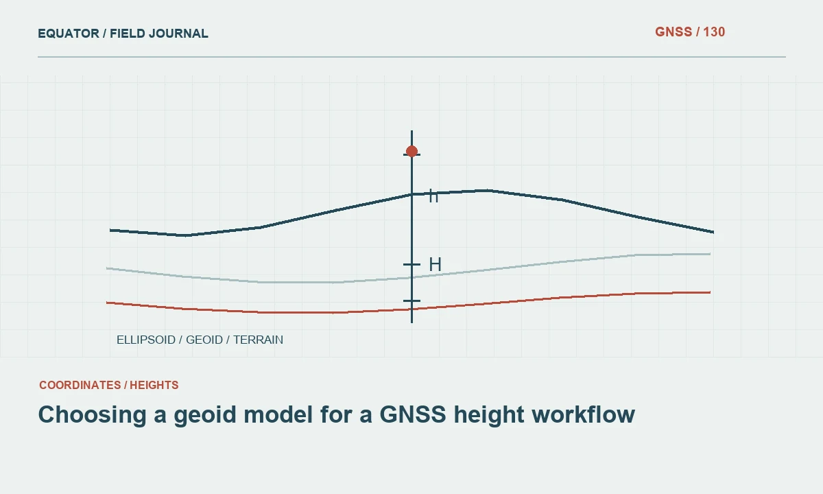
Satellite positioning normally determines an ellipsoidal height associated with a reference ellipsoid. Many engineering and mapping tasks require a different height reference, often an orthometric height related to a gravity based vertical datum. A geoid model or an approved transformation may connect those quantities. The uncertainty of that connection is part of the delivered elevation, even when the receiver's internal vertical estimate looks small.
Record the exact height convention, model name and version used. Avoid describing an elevation merely as above sea level, because that phrase does not identify a reproducible datum or transformation. If the project uses a local construction benchmark, explain how it relates to the GNSS framework. A local vertical fit may be useful, but it must be verified across the area and not hidden inside an undocumented controller setting.
Continue learning Building a GNSS error budget before fieldwork
Design independent checks for both components
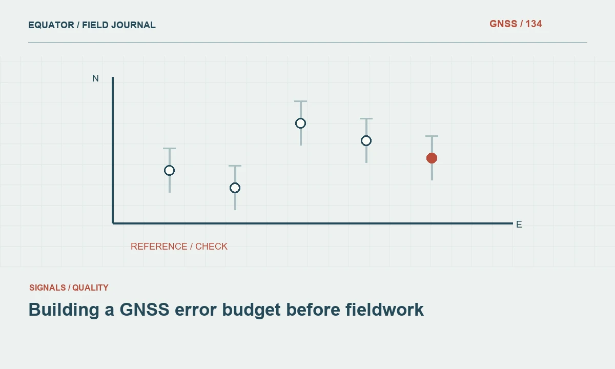
Choose check points whose coordinates and physical definitions are understood. Compare horizontal differences and height differences separately, retaining the signed components where possible. A radial horizontal distance alone conceals whether the discrepancy points consistently east or north. Likewise, a single absolute height difference conceals whether elevations are all high, all low or varying across the project. Patterns often reveal the source of a problem more clearly than a pass or fail flag.
Checks should be independent of the process being tested. A point used to determine a local transformation is not an independent test of that transformation. A second occupation from the same setup can test short term repeatability without revealing a common base coordinate error. Select different observation times, suitable independent control or another measurement technique according to the risk and the project specification.
Continue learning Choosing a geoid model for a GNSS height workflow
Review a height disagreement systematically
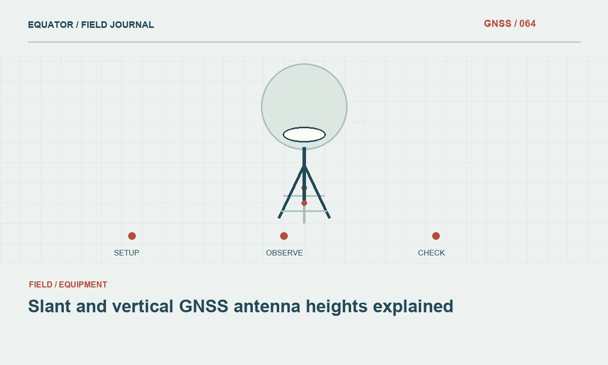
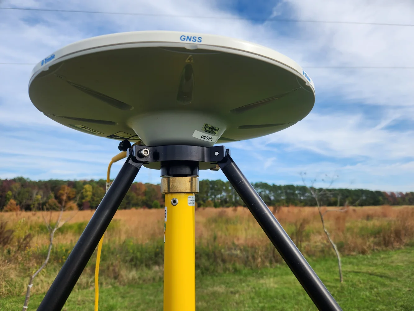
Suppose repeated GNSS occupations agree horizontally but differ from a benchmark in elevation. Check antenna height entry, measurement method, antenna reference point and whether pole tilt compensation was active and appropriate. Then inspect ellipsoidal versus orthometric height settings, geoid availability and vertical transformation parameters. Confirm that the benchmark itself is stable and that its published height refers to the same physical mark that was observed.
Do not immediately force a vertical shift to make the first check fit. Measure additional suitable points and examine whether the discrepancy is consistent or spatially variable. A constant offset suggests a different set of causes from a tilt across the site. If a local correction is accepted, document how it was derived, which points constrained it and which independent points verified the corrected result.
Continue learning Accuracy, precision and uncertainty in GNSS reports
Avoid confusing precision with deliverable fitness
A small displayed uncertainty is useful evidence about a solution under its processing assumptions. It does not certify the correct datum, a correct antenna height or the absence of a gross error. Conversely, an honest uncertainty estimate can be larger than desired while still accurately describing the measurement. The appropriate response is to improve the observation method or adjust the intended use, rather than hide the quality value in the exported file.
Report uncertainty with enough decimal places to convey the assessment but without creating false confidence. Coordinate formatting and measurement quality are separate decisions. Writing millimeter digits in a coordinate table does not establish millimeter accuracy. For elevations, preserve the underlying precision in the archive while selecting a sensible presentation convention agreed with the client and supported by the project's quality evidence.
Continue learning Slant and vertical GNSS antenna heights explained
Compare a coordinate table with a height workflow diagram
A simple review exercise is to trace one delivered elevation through each stage: physical mark, antenna reference point, ellipsoidal solution, geoid or vertical transformation and final reported height. Write the units and reference definition beside every stage. Then ask whether the uncertainty summary covers that stage or only the receiver solution. This often reveals a missing model identifier or an unexplained local offset that is invisible in a table containing only east, north and elevation columns.
Perform the same exercise for a horizontal coordinate, including projection and any local fit. The two paths share some inputs but are not identical. Keep their verification records separate enough that a successful horizontal check cannot accidentally approve the vertical chain. Where the project uses local benchmark heights, identify whether the final height is independently tied to a recognized vertical framework or only consistent with those local marks. Both outcomes can be useful, but downstream designers need the distinction to choose an appropriate use and to avoid mixing elevations from incompatible sources.
Continue learning Building a GNSS error budget before fieldwork
Deliver the context with the coordinates
Include separate horizontal and vertical quality summaries, the confidence interpretation, the reference systems and the check methodology in the handover. Where only relative height differences were tested, state that boundary clearly. Where a geoid or local vertical transformation was used, provide its identifier and any applicable area limitation. A reviewer should be able to understand the elevation workflow without reopening every controller screen.
This distinction helps downstream teams choose appropriate uses for the data. A mapping team can evaluate feature placement, a designer can review height suitability and a future surveyor can repeat checks in the same framework. Clear horizontal and vertical reporting reduces the temptation to treat one attractive precision number as a complete statement about an entire GNSS survey.
Continue learning Choosing a geoid model for a GNSS height workflow
Practical checklist
- Read the uncertainty label before the number.
- Compare a coordinate table with a height workflow diagram.
- Deliver the context with the coordinates.
Plan your GNSS setup
Compare the EQ10 and EQ20 receiver specifications, then discuss the configuration and support your project needs.
Compare GNSS receivers