Using forced centering in repeated GNSS setups
Understand what a repeatable mounting arrangement controls and which coordinate and height checks it still requires.
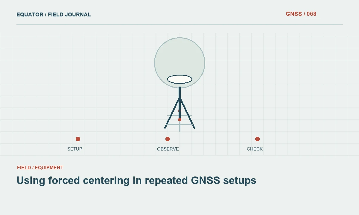
Define the repeatable interface
Forced centering uses a physical mounting arrangement intended to reproduce an instrument position over a reference location. It can reduce variability when equipment is removed and replaced, especially in repeated observations. The exact geometry depends on the mount, adapter and instrument. Document that interface rather than treating the phrase forced centering as a universal description of one identical arrangement across all equipment.
The method controls part of the physical setup, not every source of coordinate error. A repeatable mount can reproduce the wrong offset just as consistently as the correct one. Reference coordinates, antenna identification, height reduction and mount stability remain important. Begin with a drawing or description that shows the reference mark, mounting interface and antenna reference point so the crew understands what is intended to remain repeatable.
Continue learning AR stakeout: using a live view without losing coordinate discipline
Inspect the supporting structure
The mount must be attached to a structure suitable for the project. A precise coupling on an unstable support does not provide a stable reference. Inspect the monument, bracket or pillar for damage and movement. Consider environmental changes and nearby activity that could affect it between occupations. Record the condition before installing equipment so later observations can be compared with a useful baseline description.
Check the contact surfaces, screws and locating features. Dirt or damage at a small interface can alter the seating or prevent a component from locking correctly. Clean and maintain the mount according to the equipment instructions. Avoid improvised repairs that change the geometry without a new measurement and record. The repeatability claim belongs to a serviceable, correctly assembled system rather than the name printed on one component.
Continue learning Defining a local survey grid: origin, orientation and external connection
Control adapters and orientation
Identify every adapter between the fixed interface and the antenna. Swapping a component may change height, centering or orientation even if the antenna appears to occupy the same general position. Keep approved combinations labelled and preserve their geometry. A spare adapter should be verified before it is treated as interchangeable in a repeated observation series that depends on a stable antenna relationship.
Where orientation matters to the antenna model or project procedure, provide a reproducible orientation reference. Do not assume that threading an antenna into place naturally produces the same orientation each time. Follow the applicable manufacturer and processing guidance. Record deliberate changes so the analyst can distinguish an equipment event from a possible change in the point position when comparing observations across dates.
Continue learning GNSS control for bridge approaches and connecting roads
Establish the antenna relationship
Measure or otherwise establish the connection between the project mark and the antenna reference point using the approved method. A fixed mount can simplify this relationship, but it does not eliminate the need to define it. Keep the original measurements and the antenna identification. If the geometry is supplied through a calibration or installation record, preserve the record and its applicable component configuration.
Check whether the controller expects a mark to ARP height or another defined value. A mounting offset already included in a documented reduction should not be added again manually. Likewise, a new adapter should not be omitted because the previous setup used a convenient fixed number. Trace the geometry through the software fields and write a concise entry instruction for operators who did not install the mount.
Continue learning Keeping a GNSS tripod stable through a survey session
Test repeated installation
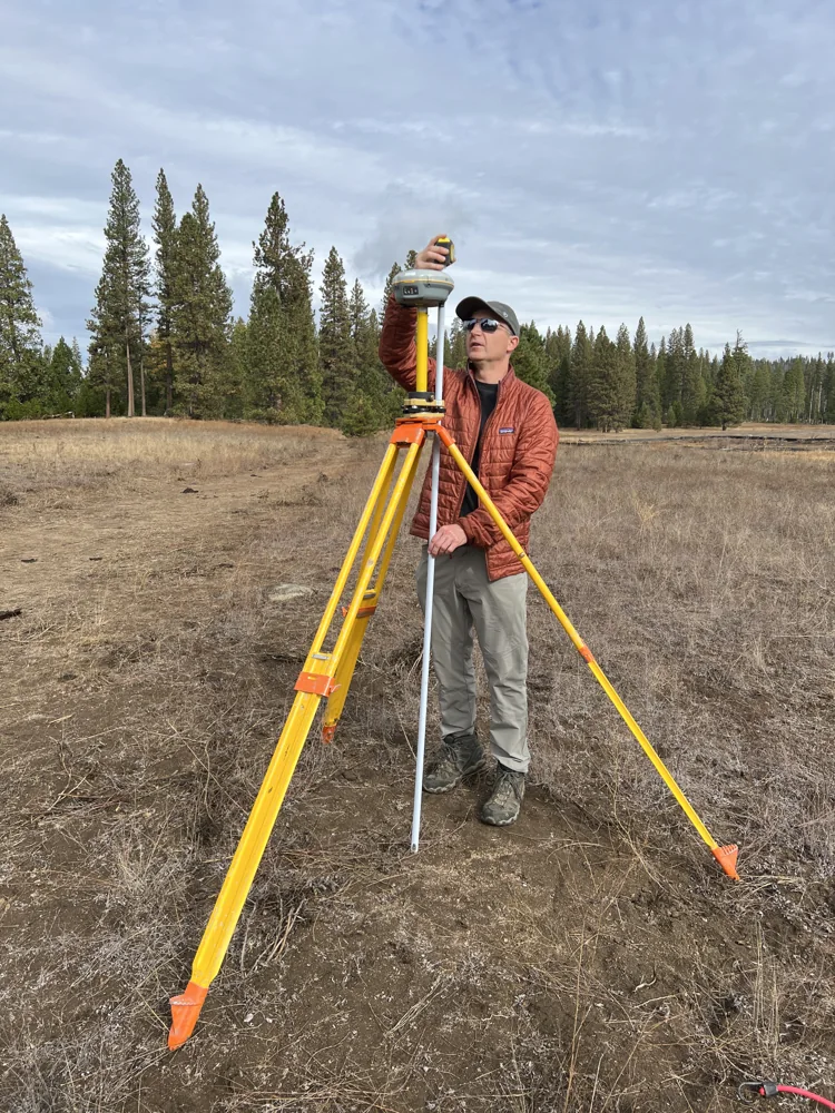
Before relying on the arrangement, remove and replace the relevant equipment under a controlled procedure and compare the resulting geometry or observations as appropriate. Preserve each installation record. A test should reflect the way the crew will actually handle the components, including the normal tightening method and inspection. A carefully staged demonstration with a different assembly sequence may not represent the daily field operation.
Use suitable coordinate checks to evaluate the complete workflow, while recognizing that common reference errors may remain shared between repeated installations. Physical repeatability and external coordinate agreement answer different questions. Report both where the project requires them. Avoid claiming that a close pair of repeated GNSS results proves the mounting geometry is correct in every component or that the reference point itself has not moved.
Continue learning AR stakeout: using a live view without losing coordinate discipline
Manage equipment changes
When an antenna, adapter or support component changes, create a clear event record. Identify the old and new equipment and the date and time of the transition. Decide which geometry measurements and field checks need repeating. Do not continue a long observation series under one equipment description if the physical relationship has changed, because that makes later discontinuities difficult to interpret.
If the mount is damaged or adjusted, suspend the assumption of repeatability until it is verified again. Preserve photographs and observations from before the change. An unexplained attempt to restore the old position may be less defensible than establishing a new documented relationship. The right response depends on the project, but the record should make the event visible rather than blending it into an apparently continuous setup history.
Continue learning Defining a local survey grid: origin, orientation and external connection
Use the method where it adds value
Forced centering is especially useful when the same location must be occupied repeatedly and setup variability matters to the work. Assess whether its installation and maintenance effort are justified for the campaign. A carefully operated conventional setup may be appropriate for some tasks, while a permanent interface may be worthwhile for repeated monitoring or control occupations. Choose according to the actual measurement requirement.
Provide recovery instructions, component identifiers and the geometry record with the survey archive. Another crew should be able to understand how to reproduce the setup and which checks remain necessary. A repeatable mounting system is valuable because it makes one part of the measurement chain more controlled. Its strongest use is within a documented workflow that also verifies the reference coordinates, antenna reduction and stability of the supporting structure.
Continue learning GNSS control for bridge approaches and connecting roads
A change in an apparently identical adapter
A team may replace a missing adapter with one that fits the same thread and appears similar in height. That mechanical fit does not establish that the antenna reference point occupies the same relationship to the mark. Measure or verify the approved geometry before treating the replacement as equivalent. Record the component identifiers and the installation date so a later coordinate discontinuity can be investigated against an actual equipment event.
If a long observation series depends on continuity, preserve the old geometry and perform appropriate overlap or comparison observations where practical. Do not erase the change by editing the equipment inventory to show only the latest adapter. A forced centering arrangement is useful precisely because its geometry is controlled. Component substitution should therefore be managed as a deliberate configuration change, with enough evidence to demonstrate whether the intended repeatable relationship has been preserved or a new documented relationship has begun.
Continue learning Keeping a GNSS tripod stable through a survey session
Practical checklist
- Describe the interface and approved adapter combination.
- Preserve mark to ARP geometry and orientation requirements.
- Reverify the arrangement after equipment or mount changes.
Plan your GNSS setup
Compare the EQ10 and EQ20 receiver specifications, then discuss the configuration and support your project needs.
Compare GNSS receivers