GNSS floodplain elevation mapping: control, terrain and vertical checks
Design elevation observations that represent the ground and connect consistently to the vertical reference required by floodplain analysis.
Start with the elevation use case
Floodplain elevation data may support terrain modelling, drainage assessment or comparison with water-level information. Clarify the intended analysis before collecting points. A general topographic map may omit small embankments or channel features that influence flow paths. Agree the required feature coverage, reference system and quality assessment with the team responsible for the hydraulic or planning work.
Do not treat a GNSS survey as a flood model by itself. Position observations describe selected physical locations at a particular time. Water behaviour also depends on additional data and modelling assumptions. The survey brief should identify which terrain features and checks the receiving analysis needs, while leaving model interpretation to the appropriate project workflow.
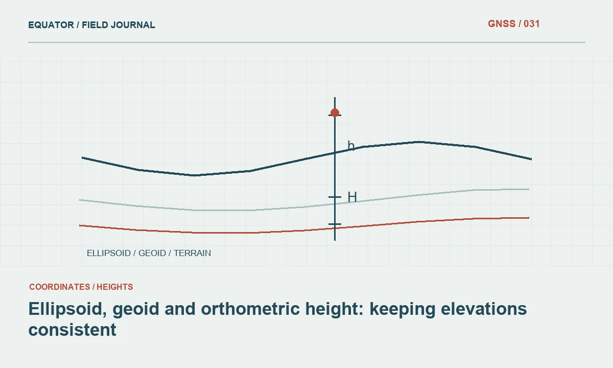
Continue learning Ellipsoid, geoid and orthometric height: keeping elevations consistent
Confirm the vertical reference first
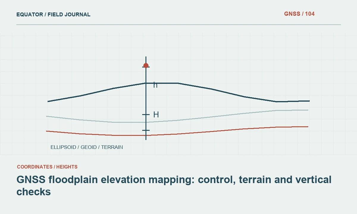
Establish whether the project requires ellipsoidal height, a national vertical datum or another defined engineering elevation. Record the geoid or vertical transformation used to connect GNSS observations to that requirement. Water-level records and existing terrain datasets may use different references. A common horizontal coordinate system does not make those heights directly comparable.
Check suitable benchmarks and review their identity, stability and published information. Investigate discrepancies before applying offsets. A value called elevation in a controller can depend on job settings that are not visible in a simple point export. Preserve those settings and model versions in the project record so the final surface can be traced back to a defined height workflow.
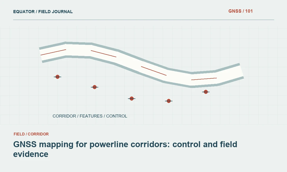
Continue learning GNSS mapping for powerline corridors: control and field evidence
Capture features that control terrain connectivity
Plan observations for levees, road embankments, channels, culverts, banks and depressions relevant to the project. A regular point pattern alone may miss a narrow crest or a drainage opening. Use breaklines and feature codes that describe how the terrain connects. Record whether a point represents bare ground, a structure, vegetation or another surface.
Discuss subsurface or inaccessible hydraulic features separately. A cover level is not a pipe invert, and a visible water surface is not the channel bed. Where direct observation is unavailable, document the source of any adopted value. Keeping these definitions clear prevents a terrain model from incorporating convenient but physically incorrect elevations at important flow-control locations.
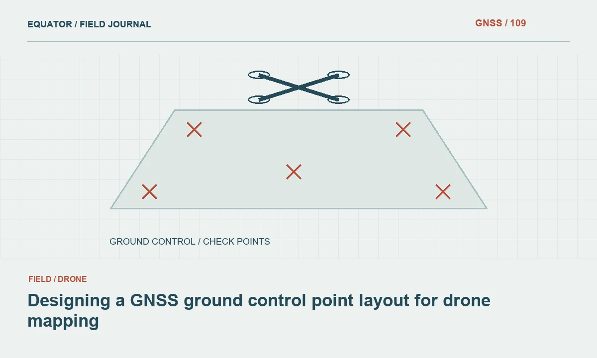
Continue learning Designing a GNSS ground control point layout for drone mapping
Adapt methods to vegetation and soft ground
Floodplains may include tall grass, trees, wet ground and standing water. These conditions affect both access and the definition of the measured surface. GNSS can position the antenna while the pole tip rests on vegetation or sinks into soft material. The field crew must establish what physical point is being observed and record limitations when bare ground cannot be identified reliably.
Evaluate satellite visibility and reflections at each observation area. Use suitable alternatives where direct rover work cannot meet the requirement or safe access is unavailable. If aerial or lidar data complement the survey, preserve method and reference information for each source. Do not assign one undifferentiated quality label to terrain assembled from substantially different observation conditions.
Continue learning Planning GNSS surveys on steep slopes
Use independent vertical checks
Observe control checks at the beginning and end of field sessions and reserve separate points for testing the completed terrain model. Choose checks that represent the surface types relevant to the analysis. Open hard ground is useful, but it may not reveal problems in vegetated or soft areas. Keep check observations independent of the surface calibration they are intended to assess.
Compare differences using the project’s approved assessment method. Examine their spatial pattern and land-cover context rather than only a single summary statistic. A consistent vertical shift suggests a different investigation from isolated errors near vegetation or breaklines. Retain the original observations and document any excluded checks with a reason, so the assessment remains reproducible.
Continue learning Ellipsoid, geoid and orthometric height: keeping elevations consistent
Build the terrain surface with explicit boundaries
Review how the modelling software connects observations across channels, water areas and gaps. A triangle spanning an unmeasured depression can erase a feature that matters to the analysis. Use suitable breaklines, boundaries and separate feature representations. Where the chosen model cannot represent a structure or near-vertical surface adequately, identify the limitation rather than forcing the geometry into an unsuitable format.
Inspect the surface in plan, profile and cross-section. Compare it with field photographs and independent observations. Check for unrealistic ridges, closed drainage paths and elevation steps at dataset joins. These reviews test the terrain representation, which is a different issue from the precision of individual GNSS points. Both need attention before the surface is used downstream.
Continue learning GNSS mapping for powerline corridors: control and field evidence
Preserve timing and change information
Record survey dates and note relevant earthworks, maintenance or changes in channel condition. Terrain datasets from different periods may not describe one consistent floodplain state. If older information is used to fill gaps, mark its coverage and date. The receiving analyst should know where the surface combines observations separated in time.
Keep measured ground, water levels and interpreted features in distinguishable layers or attributes. Water surfaces can vary rapidly and should not be mistaken for stable terrain elevations. Explain any assumptions used to represent inaccessible ground. A transparent limitation is more useful than an apparently complete surface whose critical values were inferred without a traceable basis.
Continue learning Designing a GNSS ground control point layout for drone mapping
Deliver terrain evidence with the model
Provide the coordinate and height reference definitions, control checks, independent assessment and feature coding rules. Include breaklines, survey coverage, dates and unresolved gaps alongside the terrain product. State what physical surface each elevation type represents. This information allows the floodplain analysis team to judge fitness for purpose rather than relying solely on the map’s visual detail.
Archive raw observations where available and preserve the processing and model versions used for release. When the terrain is updated, retain the previous release and document changed areas. A dependable floodplain survey connects GNSS positioning to a carefully defined ground surface and vertical reference. That connection is essential when small elevation differences influence how the data are interpreted.
Continue learning Planning GNSS surveys on steep slopes
Investigate a blocked drainage path in the model
If a terrain model shows a road embankment blocking a channel, inspect the field evidence before assuming the obstruction is real. The survey may have captured the road crest but missed a culvert opening or channel invert. Check feature codes, photographs and any separate structure measurements. A model can be internally consistent with its input points while omitting a physical connection important to the intended analysis.
Arrange a targeted follow-up when the missing feature matters and can be measured through an appropriate method. Keep the added structure information distinguishable from the ordinary ground surface, according to the receiving model’s requirements. Document the revision and its source. This resolves the actual representation problem instead of lowering nearby terrain points arbitrarily to make water appear able to pass through the embankment.
Check the receiving analyst’s preferred representation before adding the follow-up measurements. Some workflows use a terrain surface alongside a separate structure table, while others require specifically prepared geometry. Preserve the original measured values and record any derived representation. The surveyor should not invent hydraulic parameters to complete an import template. A short coordinated review of the opening, its reference and its physical definition can resolve the missing evidence while keeping survey measurement distinct from the modelling assumptions applied later.
Continue learning Ellipsoid, geoid and orthometric height: keeping elevations consistent
Practical checklist
- Confirm compatibility with the water-level vertical reference.
- Measure narrow flow-control features deliberately.
- Test the terrain with independent checks across relevant surfaces.
Plan your GNSS setup
Compare the EQ10 and EQ20 receiver specifications, then discuss the configuration and support your project needs.
Compare GNSS receivers