GNSS mapping for powerline corridors: control and field evidence
Plan corridor observations, asset identifiers and terrain coverage while respecting access constraints and the limits of GNSS measurements.
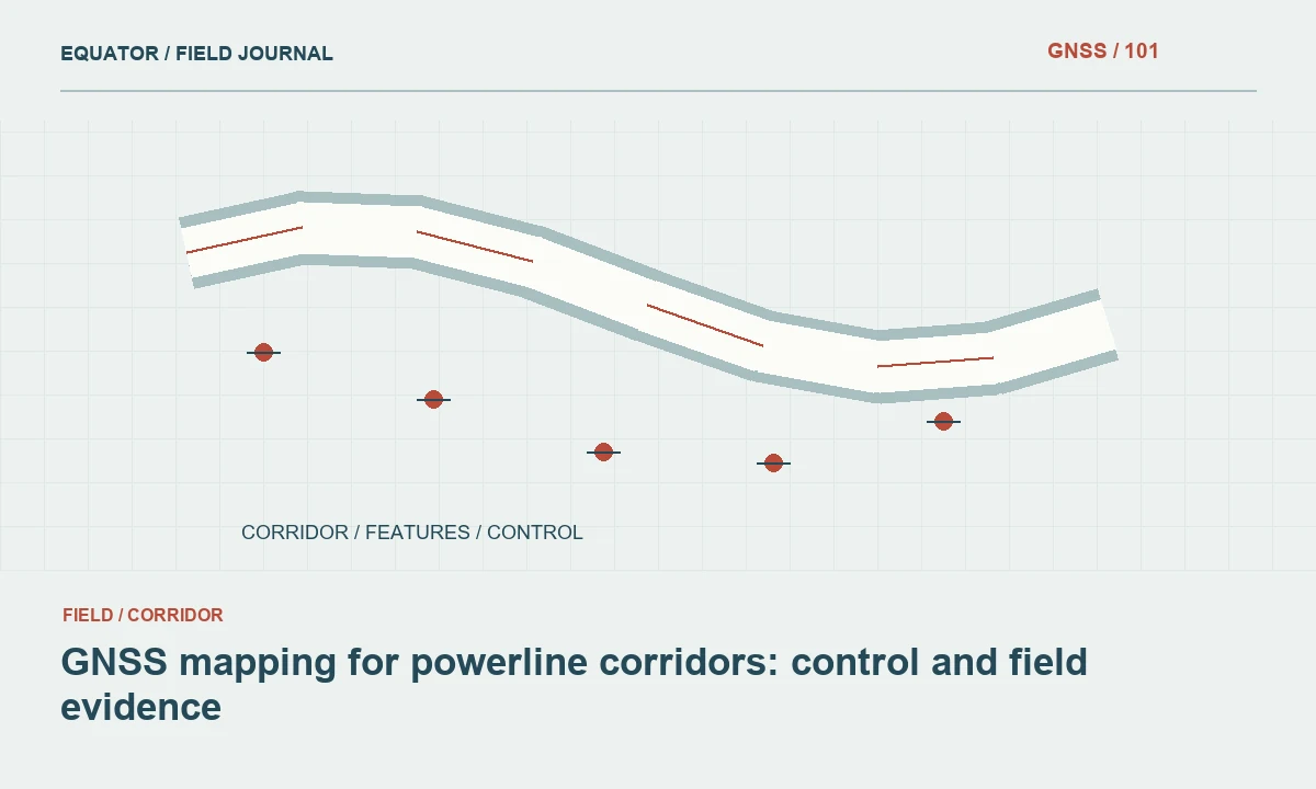
Define the corridor deliverable
A powerline corridor map may support route planning, vegetation management, asset inventory or engineering design. Agree the purpose before choosing a field observation pattern. A route overview requires different evidence from a detailed foundation or clearance study. List the terrain features, support structures, access routes and crossing information the recipient actually needs.
Keep surveyed objects separate from design proposals and interpretations. A GNSS observation at the base of a tower does not directly measure the position of every conductor or establish electrical clearance. Those tasks require an appropriate measurement method and engineering assessment. The project brief should identify which quantities are measured in the field and which are calculated or supplied by another responsible discipline.
Continue learning GNSS corridor surveys: controlling a long, changing work area
Establish access and operational boundaries
Coordinate fieldwork with the network owner and land access arrangements. Follow the approved restrictions around energised infrastructure, machinery and restricted compounds. GNSS equipment does not remove the need for those arrangements. Plan observation positions and alternative methods before the crew reaches a location where a direct occupation would conflict with site rules.
Record inaccessible segments and the reason they could not be observed. Do not fill a gap with an unlabelled estimate merely to make the corridor appear complete. Where remote observations or existing records are used, preserve their provenance and limitations. A complete map can include clearly identified unknown areas; an apparently seamless map of unsupported geometry is less useful for decisions.
Continue learning GNSS control for railway corridor mapping and survey connections
Connect long corridor sections consistently
Confirm a common horizontal reference, vertical reference and coordinate epoch where applicable. Long corridors may span several local control areas or projected coordinate zones. Decide how those transitions will be handled and document the approved method. Different coordinate magnitudes or zone identifiers should not be removed simply to make separate files look similar.
Plan overlaps between crew sections and survey dates. Use suitable independent checks to test that adjacent datasets connect as expected. Record the control version, correction method and active transformation settings for each section. When a seam appears, investigate the reference and observation evidence before applying a cosmetic shift to the newest data.
Continue learning GNSS road corridor surveys: building a consistent route dataset
Define asset observation points and identifiers
Agree what the position of a support structure represents: a centre point, a foundation corner, a marked reference or another specified object. Use the same definition throughout the inventory. Capture the network owner’s structure identifier and keep it separate from temporary survey point numbers. Photographs should show the label and enough surroundings to confirm the structure's identity.
Record multiple observations when the asset geometry requires them, rather than forcing every structure into a single point. Keep the relationship between these observations and the parent asset. If an offset is necessary, document its direction, distance and measurement method. This makes the final position interpretable and allows later crews to reproduce a check without guessing how the original point was chosen.
Continue learning GNSS utility asset mapping: position, identity and evidence
Capture terrain according to the intended analysis
Terrain coverage should follow changes in slope and important corridor features. Crests, channels, embankment toes and crossing areas may matter more than a uniform point grid. Where a terrain surface will be created, use breaklines and boundaries that describe the ground shape. Mark vegetation or obstructions that prevent direct ground observation.
Do not assume a ground rover survey alone supplies all inputs for conductor modelling or clearance assessment. Separate ground geometry from conductor observations and engineering parameters. State which surfaces or objects were actually measured and by which method. This prevents a terrain dataset from being reused later for a more demanding analysis without the evidence it would require.
Continue learning GNSS corridor surveys: controlling a long, changing work area
Evaluate GNSS conditions at each location
Corridors can alternate between open land, forests, steep valleys and developed areas. Satellite visibility and reflections therefore change along the route. Review receiver indicators together with the observation environment, repeated occupations and independent control checks. A fixed RTK status is useful but should not be the sole reason for accepting an observation beside a large structure or beneath trees.
Plan for correction communication gaps before fieldwork. Record whether observations are real-time corrected, stored for post-processing or collected by another method. When changing methods, preserve a common reference and comparable quality evidence. Avoid presenting all coordinates under a single undifferentiated accuracy label when their observation conditions and processing methods differ substantially.
Continue learning GNSS control for railway corridor mapping and survey connections
Review geometry, attributes and corridor continuity
Inspect the completed data in plan and profile. Look for missing structure identifiers, reversed line sequences, duplicate observations and unexplained elevation steps. Compare adjacent crew sections and inspect crossings carefully. A corridor line that joins the correct assets in the wrong order can be spatially plausible while operationally incorrect.
Check a selection against field photographs and source records. Confirm that geometry labels distinguish measured structures, proposed routes and inferred connections. Review the receiving system’s requirements for identifiers, units and height fields. If the delivery includes a terrain model, test it with independent observations rather than assessing only the input points used to create the surface.
Continue learning GNSS road corridor surveys: building a consistent route dataset
Deliver a corridor record that can be maintained
Provide geometry together with the data dictionary, reference definitions, survey dates, control checks and limitations. Include the asset identification rules and the meaning of each observation point. Explain any inaccessible sections or record-derived geometry. A future reviewer should understand how the dataset was assembled without reconstructing decisions from disconnected field notebooks.
Use a versioned release and preserve the original observations and photographs. Later maintenance surveys should update asset history through a defined process instead of overwriting earlier evidence indiscriminately. The value of GNSS corridor mapping comes from a consistent spatial reference connected to clearly identified objects, transparent methods and a record of the checks that support the delivered information.
Continue learning GNSS utility asset mapping: position, identity and evidence
Describe a crossing as several evidence layers
At a road crossing, the corridor team may collect ground points, structure references and visible asset identifiers. Keep these observations separate from conductor geometry and any engineering clearance calculation. A road level measured by GNSS can support the analysis, but it does not supply conductor sag, loading condition or the full three-dimensional wire position. Each input needs its own source and observation context.
Provide a crossing sketch that identifies measured features and outstanding information. Link the relevant point identifiers, photographs and survey dates. The engineering team can then combine the ground survey with appropriately obtained conductor and design data. This explicit handover avoids a common information gap in which a general corridor map is assumed to contain all the evidence required for a specialised crossing assessment simply because the crossing is shown on the plan.
For the crossing handover, list the observation method beside each input rather than describing the entire package as a GNSS survey. Ground points, visible structure references, record-derived dimensions and separately observed conductors have different provenance. Keep their dates and reference definitions available. If an input remains unavailable, mark it as outstanding in the crossing schedule. This gives the receiving team a practical completeness check and prevents a later user from assuming that every line shown in the corridor drawing was directly measured during the same field visit.
Continue learning GNSS corridor surveys: controlling a long, changing work area
Practical checklist
- Define the purpose of the corridor dataset and each asset point.
- Plan access with the network owner before fieldwork.
- Keep ground surveys separate from conductor and clearance analysis.
Plan your GNSS setup
Compare the EQ10 and EQ20 receiver specifications, then discuss the configuration and support your project needs.
Compare GNSS receivers