Planning radio line of sight for GNSS correction links
Use terrain reconnaissance and actual link tests to place correction equipment where it can support the intended work area.
Draw the actual radio path
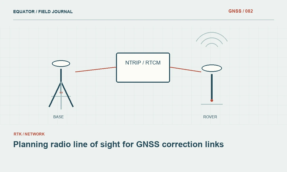
A GNSS radio link carries correction data between equipment locations. Its practical performance depends on the path, antennas, settings and local environment. Begin by drawing the base, rover work area and any approved relay arrangement on a terrain map. A straight line on a plan is a useful starting point, but it does not show ridges, buildings and vegetation that can affect the path between the antennas.
Separate the communications plan from the satellite positioning plan. A base location with excellent sky visibility may have a poor radio path to part of the project. A strong radio link does not prove that the rover has suitable satellite observations or the correct reference settings. Evaluate both systems and preserve their different tests so a later problem can be diagnosed without treating every loss of a fixed solution as a radio failure.
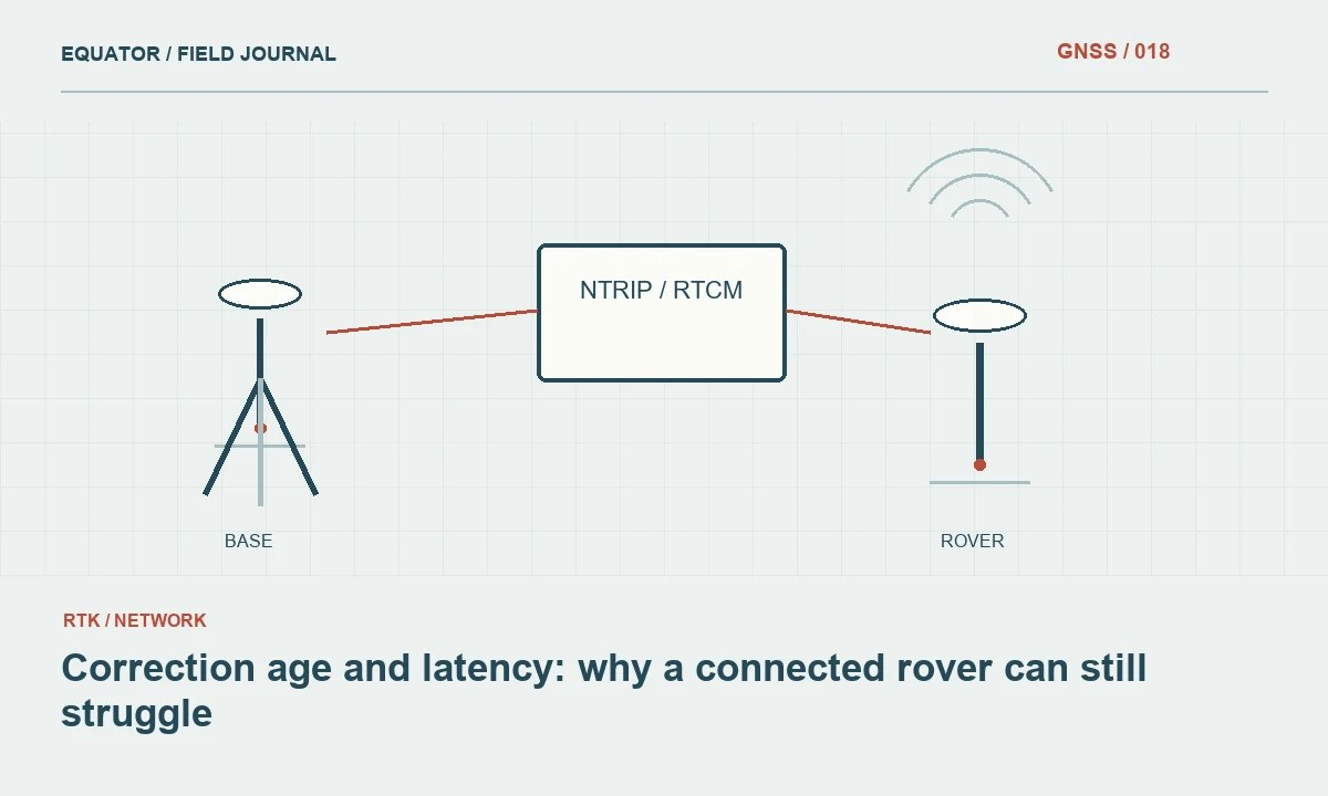
Continue learning Correction age and latency: why a connected rover can still struggle
Inspect terrain and obstacles
Use current maps, site knowledge and reconnaissance to identify likely obstructions. Include the actual antenna locations and heights in the assessment rather than using ground points alone. A ridge between the base and rover may block a path that looks short in horizontal distance. Buildings and changing vegetation can also make a previously successful arrangement unreliable in a different work zone or season.
Do not interpret visual line of sight as a universal guarantee of radio performance. The link has characteristics beyond what an operator can judge by looking between two locations. Use the equipment guidance and appropriate planning tools where the project requires them. Field tests remain important because local conditions and the assembled equipment can differ from the assumptions in a simple map based prediction.
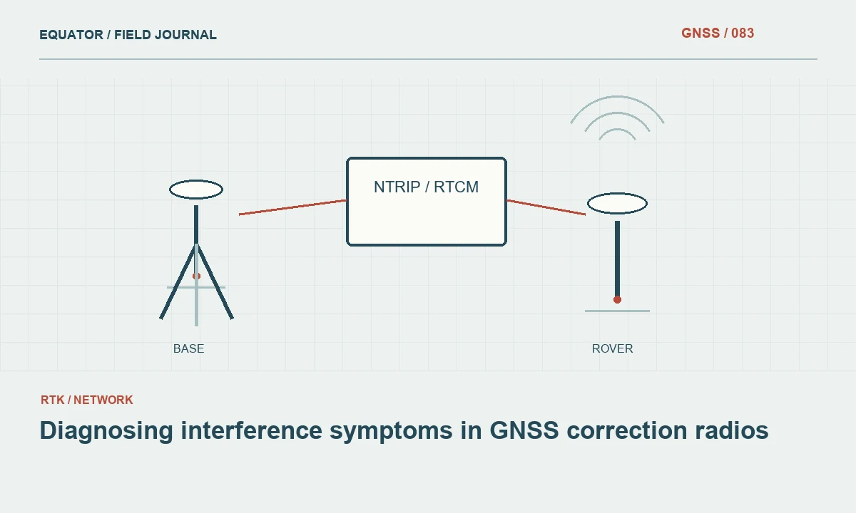
Continue learning Diagnosing interference symptoms in GNSS correction radios
Choose practical antenna locations
Consider stable support, access and the relationship to the receiver setup. Place communications equipment according to the manufacturer instructions and the approved project arrangement. Keep cables supported and avoid introducing tension or movement at the GNSS antenna. A radio improvement should not compromise the physical reference geometry or create a setup that cannot remain undisturbed during the session.
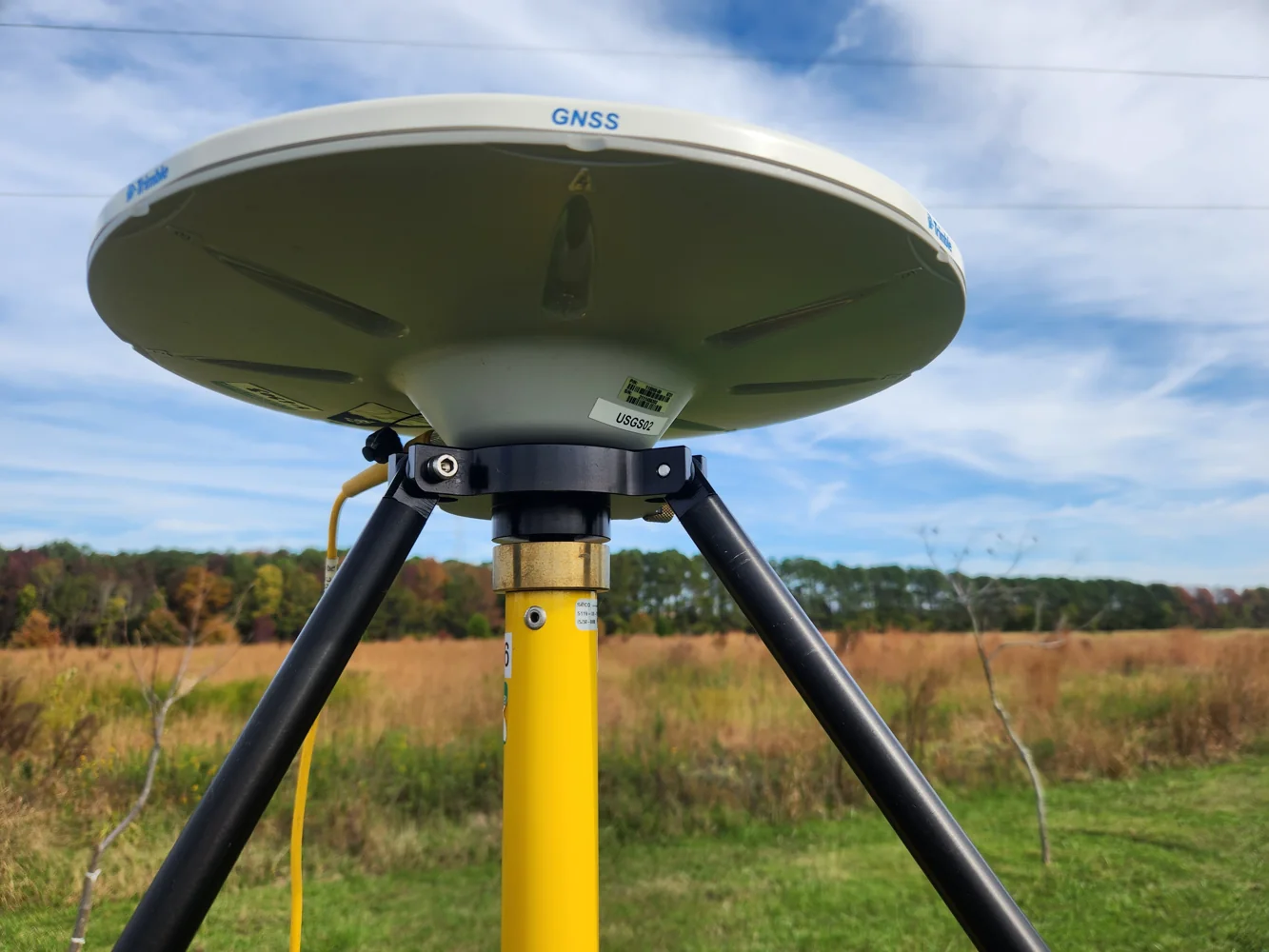
If an elevated or separate communications antenna is used, document its arrangement and test the complete system. Do not assume that any added antenna or extension cable is compatible. Components, cable losses and permitted settings belong to the communications configuration. Use approved equipment and operating conditions, and obtain the relevant service or site information rather than improvising a higher output setting as a general answer to poor coverage.
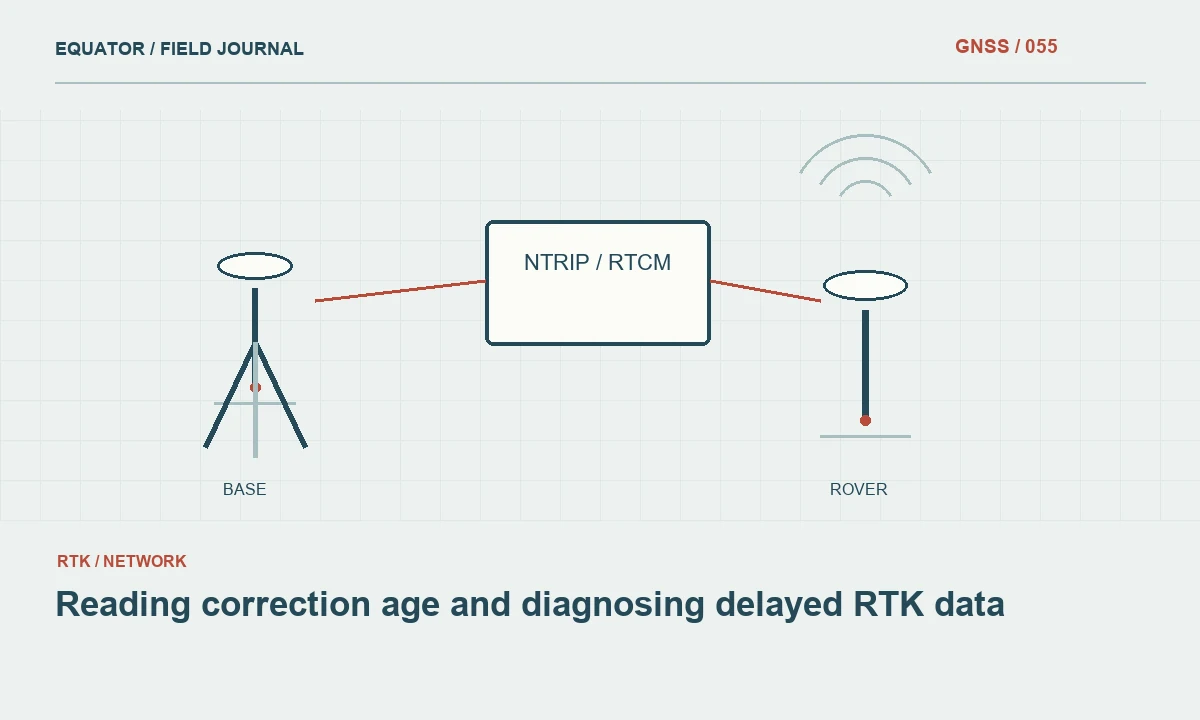
Continue learning Reading correction age and diagnosing delayed RTK data
Test representative work locations
Walk or drive the intended route with the production rover arrangement and record usable correction delivery. Include the distant and obstructed parts of the site, not only the easy area beside the base. Monitor correction age, message reception and solution state. Add known point checks to evaluate the positioning result separately from the quality of the radio connection itself.
Keep a map of successful and unsuccessful locations with timestamps and configuration. A single successful packet or brief connection does not establish reliable production coverage. Observe the link over a realistic occupation and movement pattern. Where the rover is carried differently during walking and stationary measurement, test both states if they affect antenna orientation or the position of the communications device relative to the operator and nearby objects.
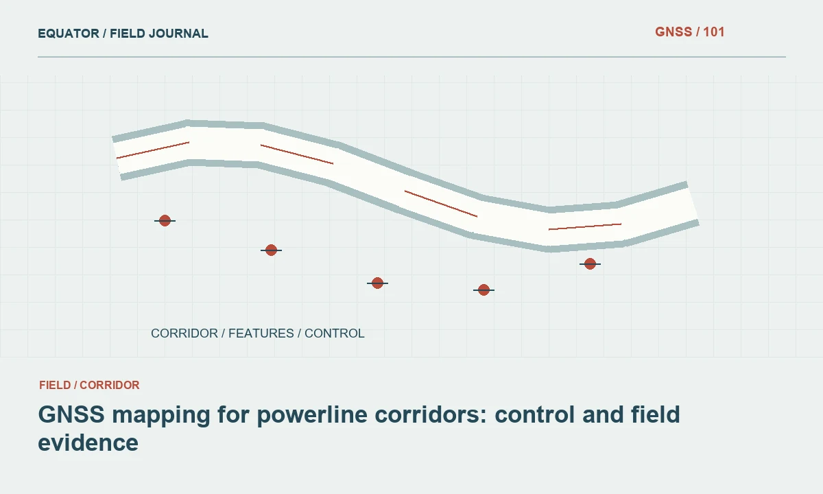
Continue learning GNSS mapping for powerline corridors: control and field evidence
Plan work zones and alternatives
If one arrangement cannot support the whole site, compare approved alternatives before production. These may include another reference location, a suitable relay configuration, internet delivery or a different measurement method for a limited area. Each option introduces setup, reference and verification work. Choose based on the complete workflow rather than only the most optimistic advertised radio range.
When dividing the project into zones, identify how their coordinates will be checked together. A base move is a new reference setup, not just a communications adjustment. Preserve coordinate sources, antenna heights and overlap checks. If a relay changes only the transport path, verify that the intended data source remains unchanged. Clear zone records prevent an operational coverage solution from becoming an unexplained coordinate discontinuity in the merged dataset.
Continue learning Correction age and latency: why a connected rover can still struggle
Diagnose failures in a controlled order
When the link fails, record the location, correction age, device state and recent movement. Check power, connectors and the approved radio settings before changing unrelated GNSS options. Compare whether the problem affects every rover or only one unit. A shared failure suggests a different investigation from a local antenna or cable problem, although the pattern alone does not identify the cause conclusively.
Change one suspected element at a time where practical and record the outcome. Moving to an open location can test whether the path is a factor, while using a known working component can help isolate hardware. Keep the coordinate system and correction source consistent during diagnosis. Otherwise a configuration change that appears to restore the link may also introduce a different reference arrangement that requires its own checks.
Continue learning Diagnosing interference symptoms in GNSS correction radios
Verify recovery and affected observations
After reliable delivery resumes, confirm the required solution state and measure a suitable check point. Mark the interruption and recovery times. Review points collected with missing or stale corrections under the project criteria. Do not accept them automatically because the radio later worked, and do not erase them before the evidence can be assessed. Their collection conditions determine their status.
If the communications arrangement changed, record the new profile and any physical changes near the base. Recheck setup geometry if equipment was moved. Preserve raw observations where the workflow requires them. A complete recovery record connects the restored radio path to a verified measurement state, which is the practical condition needed before critical production work can responsibly resume.
Continue learning Reading correction age and diagnosing delayed RTK data
Keep the coverage record useful
Include the tested configuration, work area and observed limitations in the project notes. Label untested areas explicitly. A map based on one reconnaissance day should not be presented as a permanent guarantee for all later conditions. Keep significant changes in terrain, buildings or vegetation in mind when reusing the arrangement on another campaign and repeat the relevant tests when the assumptions no longer hold.
For a corridor behind a ridge, a planned second work zone with a checked reference transition may be more dependable than repeated attempts to stretch the first link. The evidence from reconnaissance makes that choice reviewable. Radio planning succeeds when the crew knows where the link is expected to work, how to recognize an interruption and which approved action preserves both communications and coordinate consistency when conditions change.
Record the tested antenna arrangement with a photograph or sketch. A later crew may reproduce the radio settings but mount the antenna differently, creating a link that is no longer comparable to the reconnaissance test. The physical arrangement is part of the approved configuration and should be recoverable without relying on one operator's memory.
Continue learning GNSS mapping for powerline corridors: control and field evidence
Practical checklist
- Map terrain and actual antenna locations.
- Test correction delivery at difficult production locations.
- Document zone transitions and verify coordinates after recovery.
Plan your GNSS setup
Compare the EQ10 and EQ20 receiver specifications, then discuss the configuration and support your project needs.
Compare GNSS receivers