GNSS control for railway corridor mapping and survey connections
Use GNSS to support a coherent corridor reference while keeping track geometry, access and specialised measurement requirements explicit.
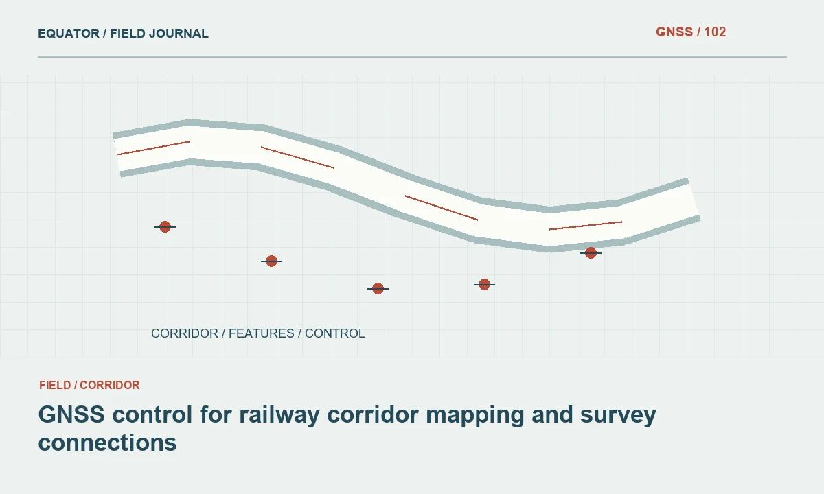
Clarify the role of GNSS in the railway project
Railway survey work can include route mapping, construction control, asset inventory and specialised track geometry measurements. These uses should not be treated as interchangeable. Define the task and its acceptance requirements with the responsible railway survey team. A general corridor dataset may be useful for planning while remaining unsuitable for a more demanding track alignment or maintenance decision.
Specify which observations will be made with GNSS and which require other instruments or approved systems. A rover point beside a rail does not automatically represent the rail centre, gauge or detailed track geometry. The survey brief should define physical targets and measurement methods clearly. This prevents a convenient position dataset from acquiring an unsupported engineering meaning during later processing.
Continue learning GNSS corridor surveys: controlling a long, changing work area
Plan access around railway operations
Coordinate access, working limits and observation times through the railway’s authorised process. Follow the applicable site arrangements around tracks, signalling equipment and electrical infrastructure. Survey planning should account for restricted observation locations instead of assuming the crew can occupy every desired point. Mark inaccessible areas in the work plan and identify acceptable alternatives.
Keep operational access information linked to survey coverage. If a planned section cannot be observed, record the gap and its status rather than blending approximate records into measured geometry without explanation. Photographs and sketches from permitted locations can help interpret the corridor. They do not replace the measurement evidence required for specialised railway engineering tasks.
Continue learning GNSS mapping for powerline corridors: control and field evidence
Maintain one documented corridor reference
Establish the approved horizontal and vertical references, local grid definitions and coordinate epoch where relevant. Railway projects can include legacy drawings, separate construction packages and control from earlier route studies. Review their compatibility before using them together. A common project name is not proof that every coordinate list belongs to the same realisation of the reference system.
Design overlaps and independent checks between work sections. Record the control version and transformation settings used by each crew. Where the corridor spans a projection boundary or uses chainage-based references, define how the relationship is maintained. Chainage, engineering offsets and map coordinates describe different aspects of location and should be connected through explicit rules.
Continue learning GNSS road corridor surveys: building a consistent route dataset
Choose control marks with future use in mind
Select marks that are stable, recoverable and outside likely disturbance where the operational setting permits it. Distinguish primary control from temporary working marks. Document descriptions, photographs and access conditions so another authorised crew can recover the same point. A mark that cannot be confidently identified is a weak reference even when its coordinate list appears precise.
Consider how planned works, vegetation maintenance or equipment installation may affect access and stability. Establish a process for checking and retiring marks after disturbance. Do not continue using a damaged or uncertain mark merely because it is convenient. A maintained status register allows the survey team to use the network coherently as the corridor changes over time.
Continue learning GNSS control for bridge approaches and connecting roads
Design observations for obstruction and reflection
Cuttings, stations, canopies, bridges and nearby structures can affect satellite visibility and signal behaviour. Conditions may differ over short distances. Assess each observation site and retain the relevant quality indicators. Independent checks and repeated occupations are important because a receiver’s fixed solution label alone cannot expose every reference, antenna setup or local signal problem.
Use total station observations, levelling or another suitable approved method where GNSS cannot support the required result. Document the connection between methods and preserve common reference definitions. Avoid an undocumented offset from a convenient open location to a target beneath a structure. The geometry of any derived position must remain understandable in the field record and final handover.
Continue learning GNSS corridor surveys: controlling a long, changing work area
Keep corridor assets and track references distinct
Create clear feature codes for structures, drainage, fencing, access features and other corridor objects. Use stable asset identifiers where the railway provides them. Define the exact point observed for each asset type. A cabinet corner, foundation reference and approximate asset centre should not all be stored under a generic point code with no explanation.
Separate observed assets from design alignments and specialised track geometry records. When a map shows a line connecting observations, explain whether that line is measured, derived or merely illustrative. Preserve photographs and notes for unusual locations. Clear semantics help prevent a later user from assuming a corridor inventory has the same status as an approved track engineering survey.
Continue learning GNSS mapping for powerline corridors: control and field evidence
Review network checks and section joins
Evaluate control observations using the project’s approved method and criteria. Look for patterns in differences across the corridor, rather than relying on a single summary value. A rotation, scale or vertical reference issue can remain hidden near one control point and become apparent farther away. Investigate the cause before adjusting delivered geometry.
Review joins between survey dates and crews, including attributes as well as positions. Check units, asset identifiers, height types and the handling of inaccessible sections. Keep rejected observations and the reasons for exclusion in the archive. The review should establish whether the dataset supports its defined corridor purpose, not merely whether the points form a visually smooth line.
Continue learning GNSS road corridor surveys: building a consistent route dataset
Provide a usable control and survey handover
Deliver the reference definitions, control schedule, observation evidence, approved versions and limitations with the corridor data. Explain mark status and which methods are suitable in obstructed areas. State the intended use of the dataset and identify specialised track measurements that were outside its scope. This makes the handover useful without overstating what GNSS observations establish.
Retain raw data where available, field notes and the history of coordinate revisions. Future work should be able to connect to the same reference and recognise changes in mark status. A railway corridor control network is a maintained spatial framework. Its reliability depends on clear responsibility, safe access, traceable observations and consistent information across the many teams that use it.
Continue learning GNSS control for bridge approaches and connecting roads
Keep route chainage and map position connected
A railway asset may be identified operationally by route and chainage while the survey stores a projected coordinate. Preserve both fields and record the source of the chainage value. A chainage marker, a calculated distance along an alignment and a legacy asset register entry may not be identical references. Do not overwrite one with another merely because their numbers are close.
When deriving chainage from coordinates, use the approved alignment version and document how offsets or branch routes are handled. Test the result at known locations and inspect transitions at junctions. A later alignment revision may change the derived chainage without moving the physical asset. Keeping the coordinate observation and the chainage derivation separate allows the inventory to be updated coherently and helps another crew understand how to recover the same object.
A useful route asset schedule therefore carries the physical observation identifier, map coordinate, route identifier, chainage source and alignment version as separate information. Review branch lines and locations where operational naming changes. Do not rely on a concatenated text label as the only record of these relationships. Test the schedule with a maintenance or survey colleague who did not collect the data. Their ability to identify the intended location from the delivered evidence is a practical check that the spatial and operational references have been connected clearly.
Continue learning GNSS corridor surveys: controlling a long, changing work area
Practical checklist
- Agree the intended railway survey use and approved methods.
- Maintain a control register with access and mark status.
- Check corridor joins and reference compatibility explicitly.
Plan your GNSS setup
Compare the EQ10 and EQ20 receiver specifications, then discuss the configuration and support your project needs.
Compare GNSS receivers