GNSS road corridor surveys: building a consistent route dataset
Plan corridor control, road feature coding and independent checks before collecting a long sequence of GNSS observations.
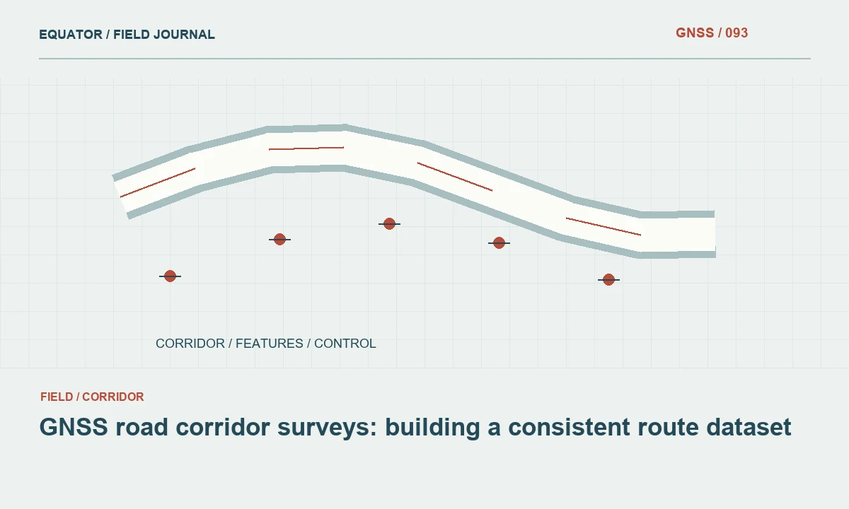
Define the road information the design needs
A road corridor survey should begin with the decisions the dataset must support. A drainage study needs reliable channel and crossfall information, while a widening design may require pavement edges, embankments, utilities and property references. Agree which objects are measured directly and which are interpreted later. A dense cloud of unnamed points can still omit the feature that controls the engineering decision.
Specify the corridor limits, junction coverage and expected handover format before fieldwork. Record whether the route is described by a design alignment, an existing centreline or a temporary chainage system. These are different references and should not be silently substituted. A written feature list allows the field crew and office processor to recognise the same roadside objects without relying on memory.
Continue learning GNSS corridor surveys: controlling a long, changing work area
Connect the entire corridor to one reference
Long routes can cross several work areas, cellular coverage zones and existing control networks. Establish the approved horizontal and vertical references for the whole job, including the coordinate epoch when relevant. Review any supplied benchmarks before using them. Similar-looking coordinates from different drawings are not evidence that the underlying reference systems agree.
Plan control so that crews can check near their daily work area without treating every temporary setup as a new independent coordinate origin. Keep stable reference points outside likely construction disturbance. Where a corridor requires a different working grid or zone, document the transition explicitly. Overlapping checks at the transition help reveal a discontinuity before it reaches the final road model.
Continue learning GNSS control for railway corridor mapping and survey connections
Build a feature coding plan
Separate breaklines, isolated objects and descriptive observations. Pavement edges, ditch inverts and embankment toes usually need connected geometry, while a sign or inspection cover is often represented as an individual feature. Use point codes that distinguish these purposes. Add attributes for side of road, surface type and visibility when those properties affect interpretation.
Test the coding system on a short representative section and import it into the intended office software. Confirm that lines connect in the correct order and that a change in feature code starts a new object where expected. This small rehearsal can prevent kilometres of ambiguous linework. Keep photographs of unusual junctions, crossings and drainage connections tied to their feature identifiers.
Continue learning GNSS mapping for powerline corridors: control and field evidence
Adapt GNSS observations to roadside conditions
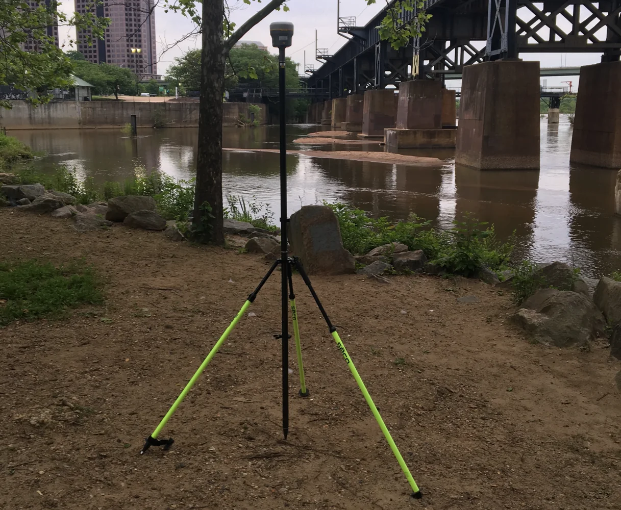
Open pavement may offer good sky visibility while retaining walls, overhead structures, trees and large vehicles change the observation environment nearby. Inspect each location rather than assuming the entire road section behaves alike. A fixed RTK status is one quality indicator, but it does not prove that a reflected signal or a mistaken antenna height has been eliminated.
Use safe positions and an approved traffic management arrangement. If the point cannot be observed reliably with GNSS, record the limitation and choose a suitable alternative measurement method. Offsets require a defined direction, distance and reference point; an improvised sideways estimate is not an equivalent observation. Preserve the relationship between the measured position and the roadside object being represented.
Continue learning Planning GNSS surveys along urban streets
Capture cross-sections and breaklines deliberately
Choose cross-section locations according to terrain changes and the design specification. Regular spacing alone may miss a culvert, a sharp ditch transition or the crest of an embankment. Record additional features where the surface changes shape. A terrain model interpolates between measurements, so the crew must collect enough structural information to constrain that interpolation.
Keep separate lines for objects that run close together, such as a pavement edge and a drain lip. Check the sequence of their points before leaving the section. An incorrect connection across a side road can create a false ridge in the terrain model. Review a simple plan and profile in the field when possible, rather than discovering an obvious coding problem after the road has reopened.
Continue learning GNSS corridor surveys: controlling a long, changing work area
Check daily joins and repeated occupations
Reobserve selected points at the beginning and end of each work period, and include overlap with the previous day's coverage. Independent occupations should involve a meaningful change in setup or observation conditions rather than repeatedly storing the same unresolved solution. Record the measured differences and compare them with the project's agreed acceptance criteria.
When a difference is unacceptable, investigate the reference, antenna height, correction source, point identity and observation environment before applying a correction. A uniform shift may suggest a reference issue, while scattered differences may indicate local observation problems. Do not average incompatible datasets merely to make a seam look smooth. Keep the original observations and the reasoning behind any approved adjustment.
Continue learning GNSS control for railway corridor mapping and survey connections
Review a road model before releasing it
Inspect the dataset in plan, profile and cross-section. Look for reversed lines, unexplained elevation steps, duplicated identifiers and gaps at junctions. Check that culvert or drainage observations describe the intended physical feature. A cover elevation, pipe invert and ground level are not interchangeable, even when they are stored close together in a drawing.
Compare independent checkpoints against the exported model, using the same reference and height type. Confirm that surface boundaries prevent interpolation across bridges, water or unmeasured areas when appropriate. Provide an uncertainty or limitation note for inaccessible sections. Review should answer whether the dataset supports the stated design use, rather than only whether the file opens successfully.
Continue learning GNSS mapping for powerline corridors: control and field evidence
Deliver evidence with the corridor geometry
Package points, linework, the coordinate reference definition, control descriptions and a concise survey report together. Explain feature codes, antenna height conventions, correction methods and the dates of observation. Include photographs or sketches for locations that are difficult to interpret from geometry alone. Preserve raw observations where available so that a later investigation can revisit the measurement process.
Use a clearly named release version and identify the corridor limits covered by that release. If a section is provisional, mark it in the dataset and report rather than leaving the recipient to infer its status. A useful road survey handover lets a designer trace an important terrain feature back to the field evidence and understand the checks that support it.
Continue learning Planning GNSS surveys along urban streets
Resolve a junction before leaving it
Consider a side road joining the surveyed corridor beside an open drain. The main road pavement edge, side road edge and drain lip may pass close together but belong to different connected features. Capture their transitions deliberately and inspect the resulting lines in the field. A processor who receives only nearby points may connect the wrong pair and create a terrain ridge across the drainage opening. Photographs should show the junction and identify which observations describe each feature.
If the crew cannot obtain a direct observation at the drain connection, record the gap rather than drawing a guessed line. Ask whether an alternative measurement can resolve it within the project method. The office reviewer can then model the area with a known limitation or request a targeted revisit. This is more efficient than repeating an entire corridor section after a hidden ambiguity appears during design.
Continue learning GNSS corridor surveys: controlling a long, changing work area
Practical checklist
- Agree corridor limits and feature codes before mobilising.
- Check reference compatibility at daily joins.
- Inspect breaklines and cross-sections before final export.
Plan your GNSS setup
Compare the EQ10 and EQ20 receiver specifications, then discuss the configuration and support your project needs.
Compare GNSS receivers